

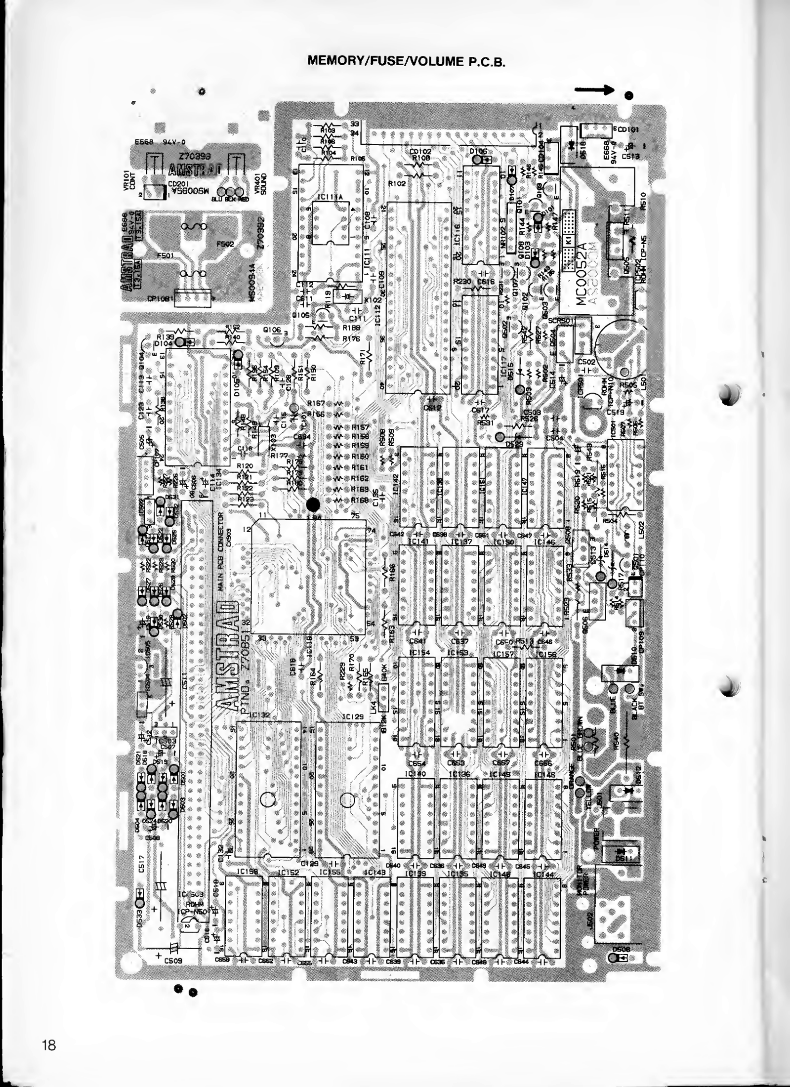
File:Amstrad PPC512 PPC640 memory and power supply PCB layout.png
Size of this preview: 436 × 600 pixels. Other resolution: 1,599 × 2,200 pixels.

Original file (1,599 × 2,200 pixels, file size: 1.52 MB, MIME type: image/png)
Summary
[edit | edit source]

Component layout of the memory/fuse/volume boards of the Amstrad PPC512 and PPC640, printed page 18 of the PPC service manual. The memory and power supply board (MC0057A in the parts list) carries the DRAM, the +5 V switching regulator and the supply electrolytics.
Source
[edit | edit source]

Rendered at 400 dpi from the hosted File:Amstrad PPC 512 PPC 640 Service Manual.pdf (Amstrad, PPC 512S / 512D, PPC 640S / 640D Personal Portable Computer Service Manual), PDF page 20, with the contrast increased.
Author
[edit | edit source]

Amstrad plc.
Licence
[edit | edit source]

Copyright Amstrad plc. Hosted for preservation and repair reference, with the source cited.
File history
Click on a date/time to view the file as it appeared at that time.
| Date/Time | Thumbnail | Dimensions | User | Comment | |
|---|---|---|---|---|---|
| current | 06:23, 2 October 2026 | | 1,599 × 2,200 (1.52 MB) | Josh (talk | contribs) | Upload for the Amstrad PCW/PPC pages |
You cannot overwrite this file.
File usage
The following 2 pages use this file:
