

File:Amstrad PPC512 PPC640 power supply schematic (service manual p. 26).png

Summary
[edit | edit source].png&veaction=edit§ion=1)
.png&action=edit§ion=1)
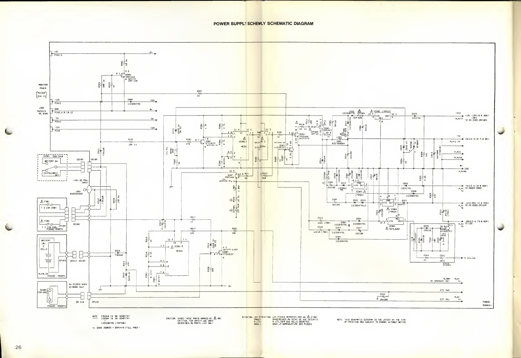
Amstrad's power supply schematic for the PPC512 and PPC640, printed across p. 26 of the service manual and joined here from the two halves of the scan. It shows the 12 V DC input jack J501, fuses F501 and F502 on the fuse board, the ten C-cell battery holder, the keyboard-shut switch SW502, the power switch SW501, the 14-way monitor power input J502, the NE556 switching and battery-alarm circuit, the +5 V switching regulator with VR501 and the SCR501 crowbar, the 78M12, 79M05, 79M12 and TA79L020 regulators, and the +12 V, +5 V, -5 V, -12 V and -20 V outputs with their tolerances.
Source
[edit | edit source].png&veaction=edit§ion=2)
.png&action=edit§ion=2)
Rendered at 250 dpi from PDF pages 33 and 34 of File:Amstrad PPC 512 PPC 640 Service Manual.pdf (described at Amstrad PPC 512 / PPC 640 Service Manual), 2026-10-02.
Author
[edit | edit source].png&veaction=edit§ion=3)
.png&action=edit§ion=3)
Amstrad plc.
Licence
[edit | edit source].png&veaction=edit§ion=4)
.png&action=edit§ion=4)
Copyright Amstrad plc. Hosted for preservation and repair reference, with the source cited.
File history
Click on a date/time to view the file as it appeared at that time.
| Date/Time | Thumbnail | Dimensions | User | Comment | |
|---|---|---|---|---|---|
| current | 06:18, 2 October 2026 | | 2,126 × 1,462 (728 KB) | Josh (talk | contribs) | Upload for the Amstrad PPC640 pages |
You cannot overwrite this file.
File usage
The following 2 pages use this file:
.png&oldid=22170)