

File:Apple Multiple Scan 720 Display adjustment locations (Service Source).png
Size of this preview: 457 × 599 pixels. Other resolution: 983 × 1,288 pixels.

Original file (983 × 1,288 pixels, file size: 81 KB, MIME type: image/png)
Summary
[edit | edit source].png&veaction=edit§ion=1)
.png&action=edit§ion=1)
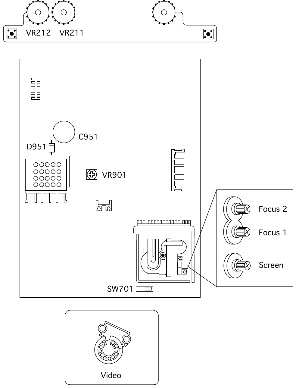
Apple's board diagram of the adjustment and check points on the Multiple Scan 720 main deflection board: VR901 (B+ adjustment), diode D951 and capacitor C951, switch SW701 (horizontal centring), the Focus 1, Focus 2 and Screen controls on the flyback transformer, and VR211/VR212 on the front control board.
Source
[edit | edit source].png&veaction=edit§ion=2)
.png&action=edit§ion=2)
File:Multiple scan 720 display.pdf, Adjustments chapter, page 6 (PDF page 83).
Author
[edit | edit source].png&veaction=edit§ion=3)
.png&action=edit§ion=3)
Apple Computer, Inc.
Licence
[edit | edit source].png&veaction=edit§ion=4)
.png&action=edit§ion=4)
Copyright Apple Computer, Inc. Figure reproduced from Apple's service documentation for repair reference, with the source cited.
File history
Click on a date/time to view the file as it appeared at that time.
| Date/Time | Thumbnail | Dimensions | User | Comment | |
|---|---|---|---|---|---|
| current | 11:47, 2 October 2026 | | 983 × 1,288 (81 KB) | Josh (talk | contribs) | Upload for Apple display pages |
You cannot overwrite this file.
File usage
The following page uses this file:
.png&oldid=23020)