

File:Apple Network Server logic board diagram (Service Guide Volume V).png

Summary
[edit | edit source].png&veaction=edit§ion=1)
.png&action=edit§ion=1)
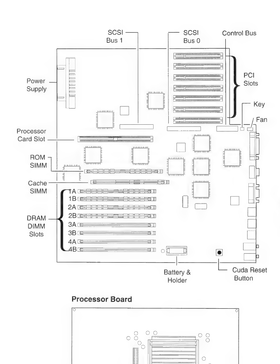
Apple's Figure 82, "Apple Network Server 500 and 700 Logic and Processor Boards": the logic board with the SCSI bus 0 and 1 connectors, control bus, PCI slots, processor card slot, ROM SIMM, cache SIMM, DRAM DIMM slots 1A-4B, battery holder and Cuda reset button, and the processor board below. Rendered at 200 dpi from printed page 217 of the Service Guide chapter and cropped.
Source
[edit | edit source].png&veaction=edit§ion=2)
.png&action=edit§ion=2)
File:Apple Service Guide Volume V (1997) Network Server 500 and 700 chapter.pdf, printed p. 217, from Internet Archive item service-guide-macintosh-computers-volume-v-june-1997-copy.
Author
[edit | edit source].png&veaction=edit§ion=3)
.png&action=edit§ion=3)
Apple Computer, Inc.
Licence
[edit | edit source].png&veaction=edit§ion=4)
.png&action=edit§ion=4)
Copyright Apple Computer, Inc. Not freely licensed. Hosted for preservation and repair reference, with the source cited.
File history
Click on a date/time to view the file as it appeared at that time.
| Date/Time | Thumbnail | Dimensions | User | Comment | |
|---|---|---|---|---|---|
| current | 06:44, 2 October 2026 | | 1,100 × 1,430 (121 KB) | Josh (talk | contribs) | Upload image; source and licence on file page |
You cannot overwrite this file.
File usage
The following page uses this file:
.png&oldid=22260)