

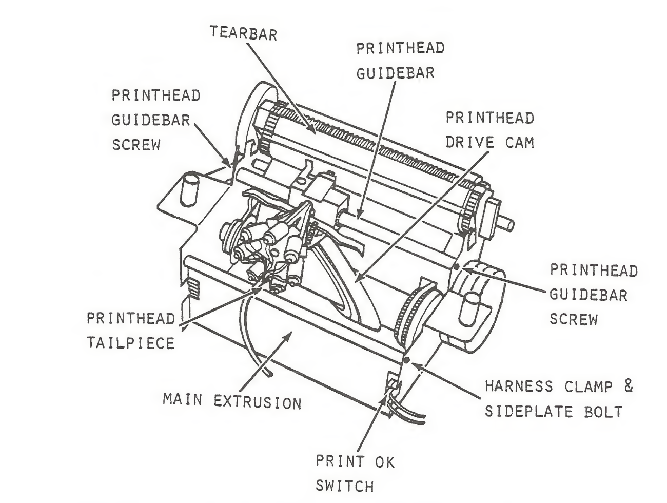
File:Atari 820 print mechanism (field service manual figure 5-5).png
Size of this preview: 795 × 599 pixels. Other resolution: 1,300 × 980 pixels.

Original file (1,300 × 980 pixels, file size: 528 KB, MIME type: image/png)
Summary
[edit | edit source].png&veaction=edit§ion=1)
.png&action=edit§ion=1)
Figure 5-5 of the ATARI 820 Printer Field Service Manual (FD100048), "Print Mechanism-Component Location": the tear bar, print head guide bar and its two screws, print head drive cam, print head tailpiece, main extrusion, harness clamp and side plate bolt, and the Print OK switch.
Source
[edit | edit source].png&veaction=edit§ion=2)
.png&action=edit§ion=2)
Rendered at 200 dpi from File:Atari 820 Printer Field Service Manual FD100048.pdf, page 60 of the PDF (manual page 5-14), and cropped, 2026-10-04.
Author
[edit | edit source].png&veaction=edit§ion=3)
.png&action=edit§ion=3)
Atari, Inc.
Licence
[edit | edit source].png&veaction=edit§ion=4)
.png&action=edit§ion=4)
Copyright Atari, Inc. Reproduced from the service manual for repair reference.
File history
Click on a date/time to view the file as it appeared at that time.
| Date/Time | Thumbnail | Dimensions | User | Comment | |
|---|---|---|---|---|---|
| current | 15:41, 4 October 2026 | | 1,300 × 980 (528 KB) | Josh (talk | contribs) | Upload Atari 820 service manual figure with source |
You cannot overwrite this file.
File usage
The following page uses this file:
.png&oldid=24165)