

File:Atari Megafile controller C103166 power connectors (schematic detail).png

Summary
[edit | edit source].png&veaction=edit§ion=1)
.png&action=edit§ion=1)
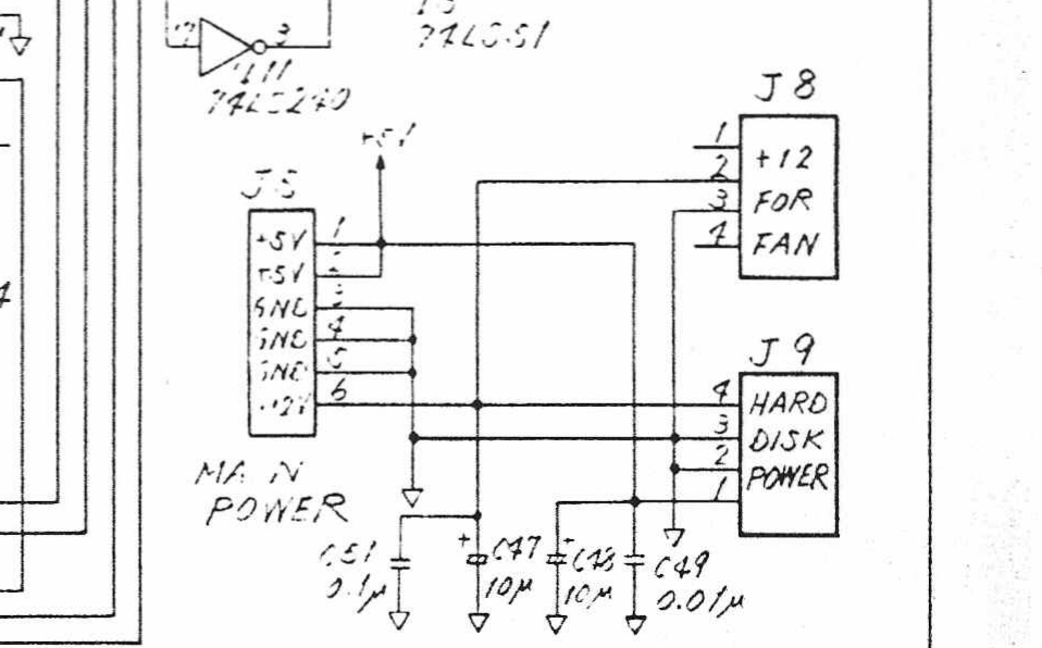
Detail of Atari Corporation's Schematic Diagram, Megafile 60 (RLL), drawing C103166 Rev. 4 (drawn 23 March 1988), showing the power side of the Megafile controller board: J5 "Main Power" (+5 V on pins 1 and 2, ground on pins 3 to 5, +12 V on pin 6), J8 "+12 for fan", J9 "Hard Disk Power", and the decoupling capacitors C47 (10 µF), C48 (10 µF), C49 (0.01 µF) and C51 (0.1 µF). Rendered at 300 dpi from page 3 of the scan and cropped; converted to greyscale.
Source
[edit | edit source].png&veaction=edit§ion=2)
.png&action=edit§ion=2)
Internet Archive, item Atari_Megafile_30_60_Service_Manual_RLL_undated, PDF page 3 (retrieved 2026-10-06). The full document is hosted here as File:Atari Megafile 30 and 60 Service Manual (Schaltungsdienst Lange).pdf and described on Atari Megafile Documentation.
Author
[edit | edit source].png&veaction=edit§ion=3)
.png&action=edit§ion=3)
Atari Corporation.
Licence
[edit | edit source].png&veaction=edit§ion=4)
.png&action=edit§ion=4)
Copyright Atari Corporation. Manufacturer drawing, hosted for preservation and repair reference with the source cited.
File history
Click on a date/time to view the file as it appeared at that time.
| Date/Time | Thumbnail | Dimensions | User | Comment | |
|---|---|---|---|---|---|
| current | 11:14, 6 October 2026 | | 958 × 596 (133 KB) | Josh (talk | contribs) | Upload for the Atari Megafile pages |
You cannot overwrite this file.
File usage
The following page uses this file:
.png&oldid=24752)