

File:Atari XMM801 power supply schematic (FSM Figure 18).png

Summary
[edit | edit source].png&veaction=edit§ion=1)
.png&action=edit§ion=1)
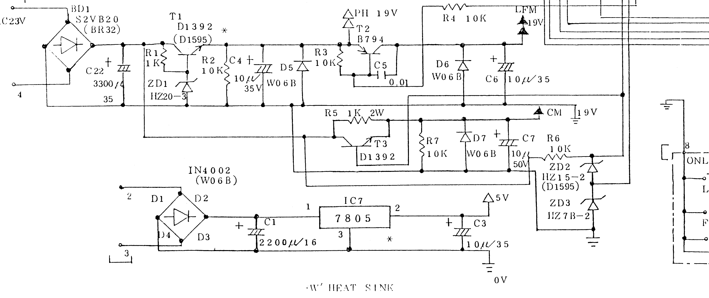
Power supply section of the Atari XMM801 main control board circuit diagram (Figure 18, page 10 of Atari's XMM801 Field Service Manual, CO 70435, October 1985): the S2VB20 bridge BD1 and 2SD1392 pass transistor T1 that make the 19 V head and motor supplies, and the 1N4002 bridge D1-D4 with the 7805 regulator IC7 that make +5 V. Rendered at 300 dpi from the scan and cropped. The reservoir capacitor after BD1 is labelled C22 on this drawing; the manual's parts list and board layout call it C2.
Source
[edit | edit source].png&veaction=edit§ion=2)
.png&action=edit§ion=2)
Internet Archive item atari-xmm-801-field-service-manual-atari-corp, PDF page 16, retrieved 2026-10-06. The complete manual is hosted here as File:Atari XMM801 Field Service Manual C070435.pdf.
Author
[edit | edit source].png&veaction=edit§ion=3)
.png&action=edit§ion=3)
Atari Corp.
Licence
[edit | edit source].png&veaction=edit§ion=4)
.png&action=edit§ion=4)
Copyright Atari Corp. Hosted for preservation and repair reference, with the source cited.
File history
Click on a date/time to view the file as it appeared at that time.
| Date/Time | Thumbnail | Dimensions | User | Comment | |
|---|---|---|---|---|---|
| current | 11:14, 6 October 2026 | | 2,261 × 952 (71 KB) | Josh (talk | contribs) | Power supply schematic rendered from the Atari XMM801 Field Service Manual |
You cannot overwrite this file.
File usage
The following page uses this file:
.png&oldid=24758)