

File:Professional 350 system module and card cage (DEC Figure 5-2).png

Summary
[edit | edit source].png&veaction=edit§ion=1)
.png&action=edit§ion=1)
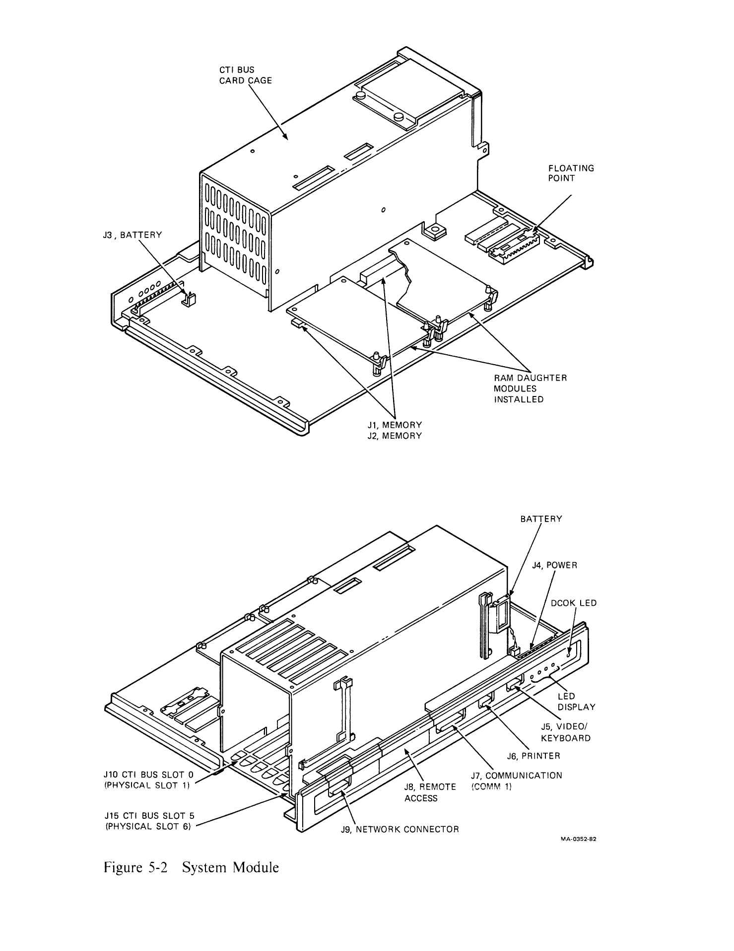
Two views of the Professional 350 system module with its CTI bus card cage: the J3 battery connector and the battery pack, the RAM daughter modules on J1 and J2, the floating point adapter, the J4 power connector, the DCOK LED and LED display, and the rear I/O connectors J5 to J9. Rendered from DEC's Professional 300 Series Technical Manual, Volume 1, EK-PC300-V1-001, Figure 5-2, p. 5-2.
Source
[edit | edit source].png&veaction=edit§ion=2)
.png&action=edit§ion=2)
File:Professional 300 Series Technical Manual Volume 1 (EK-PC300-V1-001).pdf, PDF page 52, from https://bitsavers.org/pdf/dec/pdp11/pro3xx/ (retrieved 2026-10-02)
Author
[edit | edit source].png&veaction=edit§ion=3)
.png&action=edit§ion=3)
Digital Equipment Corporation.
Licence
[edit | edit source].png&veaction=edit§ion=4)
.png&action=edit§ion=4)
Copyright Digital Equipment Corporation, 1985. Reproduced from the manufacturer's manual for repair reference, with the source cited.
File history
Click on a date/time to view the file as it appeared at that time.
| Date/Time | Thumbnail | Dimensions | User | Comment | |
|---|---|---|---|---|---|
| current | 02:38, 2 October 2026 | | 1,479 × 1,914 (130 KB) | Josh (talk | contribs) | Pro 350 system module from DEC TM vol 1 fig. 5-2 |
You cannot overwrite this file.
File usage
The following 3 pages use this file:
.png&oldid=21594)