

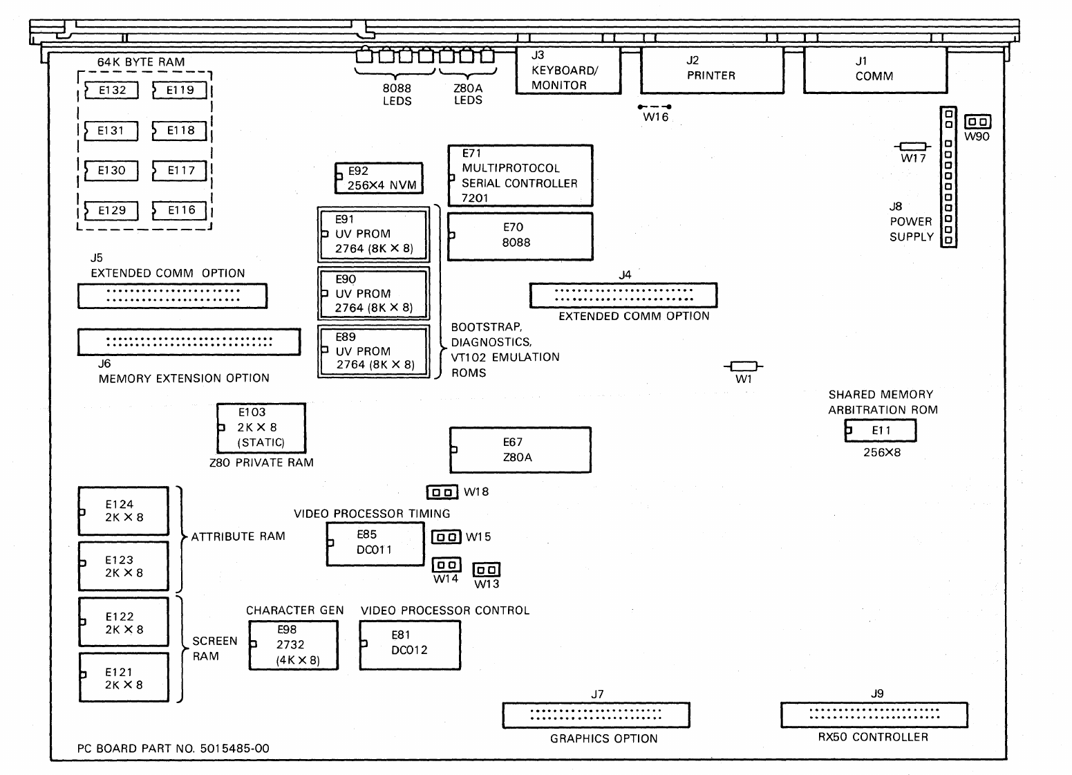
File:Rainbow 100 system module layout (DEC Figure 4-2).png
Size of this preview: 800 × 578 pixels. Other resolution: 1,551 × 1,121 pixels.

Original file (1,551 × 1,121 pixels, file size: 108 KB, MIME type: image/png)
Summary
[edit | edit source].png&veaction=edit§ion=1)
.png&action=edit§ion=1)
Physical layout of the Rainbow 100 (PC100-A) system module, PC board 5015485-00: RAM, ROM, NVM, processor and video chip locations with their E numbers, the option connectors J4 to J9 and the 8088 and Z80A diagnostic LEDs. Rendered from DEC's Rainbow 100 Technical Manual, EK-PC100-TM-001, Figure 4-2, p. 4-4.
Source
[edit | edit source].png&veaction=edit§ion=2)
.png&action=edit§ion=2)
File:Rainbow 100 Technical Manual (EK-PC100-TM-001).pdf, PDF page 103, from https://bitsavers.org/pdf/dec/rainbow/ (retrieved 2026-10-02)
Author
[edit | edit source].png&veaction=edit§ion=3)
.png&action=edit§ion=3)
Digital Equipment Corporation.
Licence
[edit | edit source].png&veaction=edit§ion=4)
.png&action=edit§ion=4)
Copyright Digital Equipment Corporation, 1984. Reproduced from the manufacturer's manual for repair reference, with the source cited.
File history
Click on a date/time to view the file as it appeared at that time.
| Date/Time | Thumbnail | Dimensions | User | Comment | |
|---|---|---|---|---|---|
| current | 01:56, 2 October 2026 | | 1,551 × 1,121 (108 KB) | Josh (talk | contribs) | Rainbow 100 system module layout from DEC TM fig. 4-2 |
You cannot overwrite this file.
File usage
The following 2 pages use this file:
.png&oldid=21425)