

File:VT100 interconnection diagram (EK-VT100-J1-001).png
Summary
[edit | edit source].png&veaction=edit§ion=1)
.png&action=edit§ion=1)
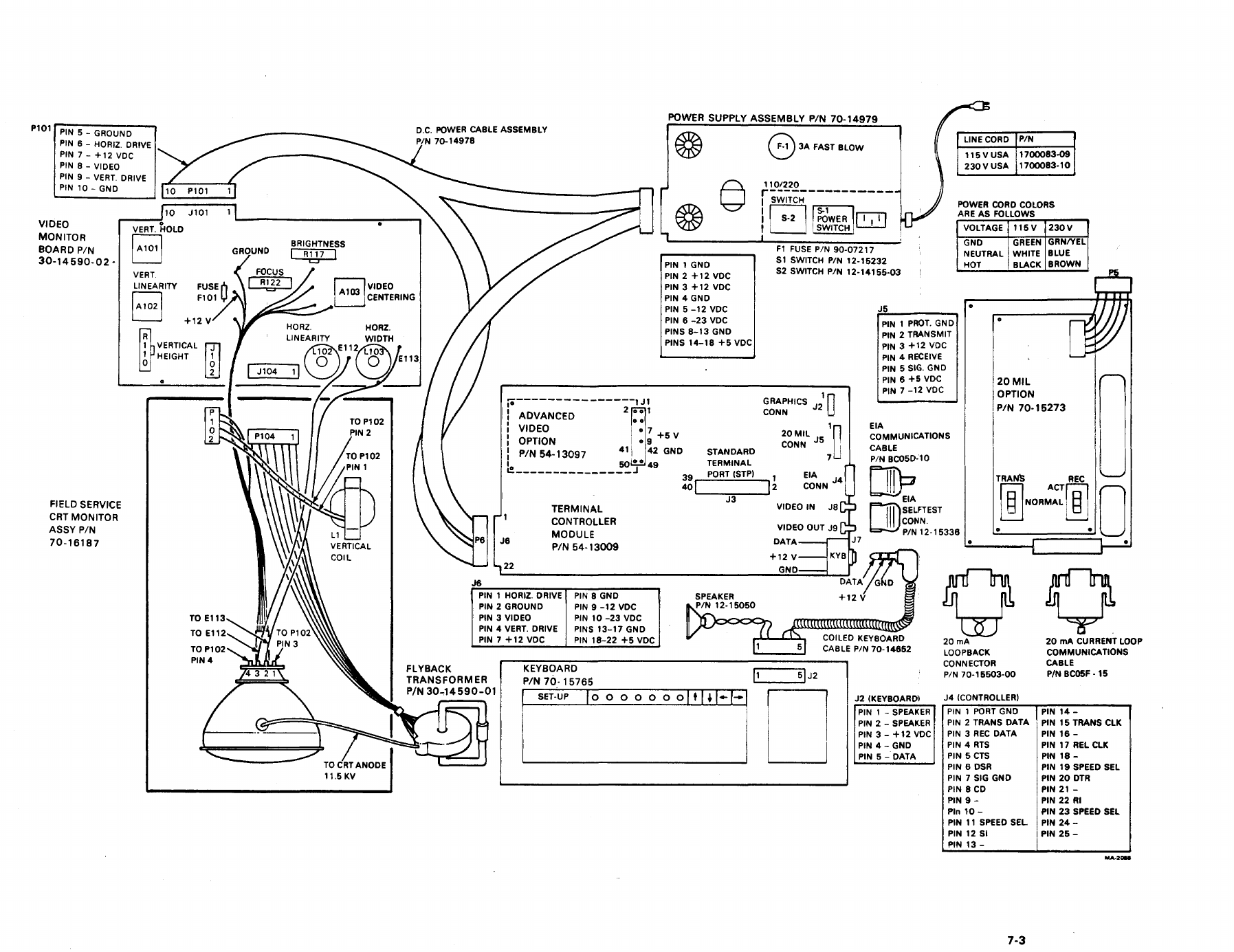
DEC's VT100 interconnection diagram (drawing MA-2088): the Ball video monitor board 30-14590-02 and its controls, flyback transformer 30-14590-01 (CRT anode 11.5 kV), power supply assembly 70-14979 with its 3 A fuse and 110/220 switch, the pin assignments and voltages of the power supply, terminal controller J6, monitor P101, keyboard J2 and communications connectors, and the loopback connectors. Page 7-3 of the VT100 Mini Maintenance Hardware Guide, EK-VT100-J1-001, September 1978, rendered from the scan.
Source
[edit | edit source].png&veaction=edit§ion=2)
.png&action=edit§ion=2)
File:VT100 Mini Maintenance Hardware Guide (EK-VT100-J1-001).pdf, p. 7-3 (PDF page 28).
Author
[edit | edit source].png&veaction=edit§ion=3)
.png&action=edit§ion=3)
Digital Equipment Corporation.
Licence
[edit | edit source].png&veaction=edit§ion=4)
.png&action=edit§ion=4)
Copyright Digital Equipment Corporation. Manufacturer documentation, used to identify the product and for repair reference.
File history
Click on a date/time to view the file as it appeared at that time.
| Date/Time | Thumbnail | Dimensions | User | Comment | |
|---|---|---|---|---|---|
| current | 02:13, 2 October 2026 | | 1,795 × 1,385 (311 KB) | Josh (talk | contribs) | Interconnection diagram from the VT100 Mini Maintenance Hardware Guide |
You cannot overwrite this file.
File usage
The following 2 pages use this file:
.png&oldid=21481)