
PDP-11/34
The PDP-11/34 is a Unibus PDP-11 minicomputer that Digital Equipment Corporation introduced in 1976 as a cheaper follow-on to the PDP-11/35 and 11/40, alongside the smaller PDP-11/04.[1] Its KD11-E processor fits on two hex-height modules and includes the extended instruction set (hardware multiply, divide and multiple shifts) and memory management, which extends memory from 28K to 124K words.[2] The PDP-11/34A of 1978 uses the KD11-EA module set, which adds the connections for the FP11-A floating-point processor and absorbs the separate sack time-out module; DEC says the two are functionally the same.[2][1] Wikipedia dates an 11/34C with a cache memory option to the same year; DEC's cache for the 11/34A is the KK11-A.[1][4]
 | |
| PDP-11/34 with the optional KY11-LB programmer's console (Autopilot, CC BY-SA 3.0) | |
| Specifications | |
|---|---|
| Manufacturer | Digital Equipment Corporation |
| Type | 16-bit minicomputer |
| Released | 1976; PDP-11/34A 1978[1] |
| CPU | KD11-E (M7265, M7266); KD11-EA (M8265, M8266) in the 11/34A[2] |
| Memory | MOS (MS11-EP, FP, JP) or core (MM11-CP, DP); 28K words, 124K words with memory management[2] |
| Storage | — |
| Display | — |
| Sound | — |
| Power | H765 power system in the BA11-K box, or H777 in the BA11-L box[3] |
| OS / Firmware | — |
| Predecessor | PDP-11/35 and PDP-11/40[1] |
The basic machine has no switches and lights. A simple KY11-LA operator's console carries a power switch, HALT/CONT and BOOT/INIT, and the M9301 bootstrap/terminator module lets a serial terminal act as a programmer's console; the KY11-LB programmer's console with keypad and LED display was an option.[2] Restoration means dealing with the H765 power system and its regulators, a wire-wrapped backplane and fifty-year-old memory; see PDP-11/34 Power Supply Restoration, PDP-11/34 General Maintenance and PDP-11/34 Troubleshooting Guide.
Configuration
edit| Unit | 11/34 | 11/34A |
|---|---|---|
| Processor | KD11-E: M7265, M7266 | KD11-EA: M8265, M8266 |
| Sack time-out | M8264 module | Built into the KD11-EA |
| Console | KY11-LA operator's console; KY11-LB programmer's console optional | Same |
| Bootstrap and terminator | M9301-YA, -YB or -YF at the start of the Unibus; M9302 at the end | Same |
| Memory | MS11-EP, FP, JP MOS (4K, 8K, 16K words) or MM11-CP, DP core (8K, 16K) | Same |
| Box and supply | BA11-K (10½ in, H765) or BA11-L (5¼ in, H777) | Same, with uprated supplies for the FP11-A |
| Backplane | DD11-PK, 9 slots | Same |
[2][3] The 11/34A user's manual notes that the power supplies were uprated for the floating-point unit; in the 10½-inch box this means two H7441 +5 V regulators of 32 A in place of the 11/34's 25 A H744s, and a 5410864-YA distribution board.[2][5]
Hardware
editBackplane and Unibus
editThe DD11-PK is a 9-slot hex backplane. Slots 1 and 2 are wired for the processor; the rest mix standard Unibus slots, modified Unibus slots for memory and small peripheral controller (SPC) slots. The DD11-DK is the same backplane without the dedicated processor slots, used for expansion, and the DD11-CK is a 4-slot expander.[6] Power reaches each backplane through two 15-pin and one 6-pin Mate-N-Lok connectors from the power supply's distribution board.[6] Each unused SPC slot needs a G727 grant continuity card in connector D, or the bus grant chain is broken.[7]
The KD11-E and KD11-EA have no Unibus termination of their own, which is why an M9301 terminator with bootstrap ROM must sit at the processor end of the bus and an M9302 at the far end.[2][8]
Bootstrap ROM
editThe M9301 holds 512 words of ROM with CPU diagnostics, bootstrap loaders for the common devices and a console emulator. The -YA version suits OEM users, the -YB end users and the -YF either.[2] On power-up it runs five processor tests and prints R0, R4, R6 and R5 on the console terminal followed by a $ prompt.[7]
Memory
editThe MS11-EP, FP and JP are single hex boards of MOS memory (4K, 8K and 16K words) and lose their contents when power is removed unless the H775 battery backup unit is fitted. The MM11-CP (8K) and MM11-DP (16K) are core memories with a hex motherboard and a daughterboard carrying the core plane.[2] MOS memory in the 11/34 uses separate +5B, +15B and −15B refresh supplies on the backplane; in a 10½-inch box without battery backup these are jumpered to the normal rails.[5]
Power
editIn the BA11-K the H765 power system supplies the regulators: one H745 −15 V regulator and two H744 (11/34) or H7441 (11/34A) +5 V regulators, with an H754 or H785 in the fourth slot depending on configuration. The first +5 V regulator feeds the processor backplane and the second all the others.[5][9] See PDP-11/34 Power Supply Restoration.
Known problems
edit- Power line monitor failure. The 5411086 board in the H765, which makes +15 V and the AC LO, DC LO and line-clock signals, takes its AC through its edge connector and has no fuse ahead of its bridge rectifier; a shorted bridge burns the connector traces.[10][11]
- H744 regulators. The commonest fault reported by restorers is the bridge rectifier; aged output capacitors make a regulator whine.[12][13]
- Backplane solder joints. Some DD11-PK backplanes have wire-wrap pins that were never properly wetted by the solder, giving intermittent opens such as a broken NPG chain.[14]
- Bus grants. A missing grant card, or a missing NPG jumper at CA1–CB1 after a DMA controller is taken out, hangs the Unibus with the RUN light on.[15]
Documentation
edit- PDP-11/34 System User's Manual, EK-11034-UG-001: File:PDP-11-34 System User's Manual (EK-11034-UG-001).pdf
- PDP11/34A Power System, EK-1134A-TM-002: File:PDP-11-34A Power System Description (EK-1134A-TM-002).pdf
- H765 power supply print set: File:H765 Power Supply Print Set (Rev R, 1977).pdf
- H744 regulator engineering drawings: File:H744 Regulator Engineering Drawings (1974).pdf
Gallery
edit-
 Modules in the Unibus backplane (Autopilot, CC BY-SA 3.0)
 -
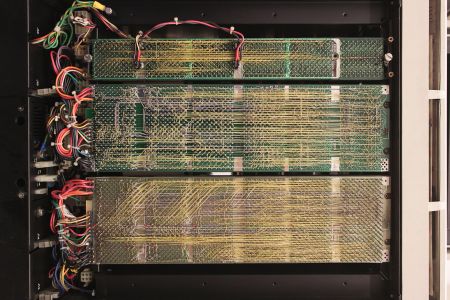 Wire-wrap side of the backplanes (Autopilot, CC BY-SA 3.0)
 -
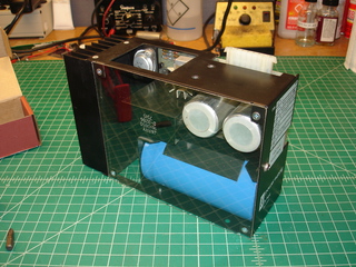 H744 +5 V regulator (Jonathan Chapman, Glitch Works)


.jpg)
Related pages
editReferences
edit- ↑ 1.0 1.1 1.2 1.3 1.4 "PDP-11", Wikipedia, en.wikipedia.org/wiki/PDP-11. Dates of the 11/34, 11/34A and 11/04, the 11/34C cache option, place in the range.
- ↑ 2.00 2.01 2.02 2.03 2.04 2.05 2.06 2.07 2.08 2.09 Digital Equipment Corporation, PDP-11/34 System User's Manual, EK-11034-UG-001, July 1977, chapter 1, pp. 1-1 to 1-9 (File:PDP-11-34 System User's Manual (EK-11034-UG-001).pdf).
- ↑ 3.0 3.1 DEC, EK-11034-UG-001, section 1.2.7, p. 1-9. Mounting boxes and power supplies.
- ↑ Bitsavers directory bitsavers.org/pdf/dec/pdp11/1134/ (KK11-A cache memory user's guide EK-KK11A-UG-001), retrieved 2 October 2026.
- ↑ 5.0 5.1 5.2 Digital Equipment Corporation, PDP11/34A Power System, EK-1134A-TM-002, second edition July 1977, sections 1.4 to 1.6 and 2.5 to 2.7, Tables 1-2 and 1-3 (File:PDP-11-34A Power System Description (EK-1134A-TM-002).pdf).
- ↑ 6.0 6.1 DEC, EK-11034-UG-001, chapter 4, sections 4.2 to 4.2.2.1, Figures 4-1 and 4-2 and Table 4-1, pp. 4-1 to 4-3.
- ↑ 7.0 7.1 DEC, EK-11034-UG-001, chapter 6, sections 6.1.3 and 6.2.1, pp. 6-2 to 6-4.
- ↑ "PDP-11/34", Computer History Wiki, gunkies.org/wiki/PDP-11/34. UNIBUS termination.
- ↑ "H765 Power System", Computer History Wiki, gunkies.org/wiki/H765_Power_System. Regulator positions in the BA11-K harness.
- ↑ Jonathan Chapman, "Repairing the PDP-11/10 Power Supply", Glitch Works, 5 June 2019, users.glitchwrks.com. H765 5411086 failure in a BA11-K.
- ↑ "DEC Power Line Monitor", Computer History Wiki, gunkies.org/wiki/DEC_Power_Line_Monitor. Unfused components on the 5411086.
- ↑ Mattis Lind, "Re: Testing a H744 Regulator on The Bench", cctalk mailing list, 30 December 2021, mail-archive.com. Rectifier bridge as the commonest H744 fault.
- ↑ Rob Jarratt, "RE: Source for replacement caps in H744 regulators", cctalk mailing list, 6 January 2022, mail-archive.com. Whining regulator and unstable ESR on the output capacitors.
- ↑ Jörg Hoppe, "Trying to fix a DEC PDP-11/34 backplane – diagnosis", retrocmp.com, retrocmp.com.
- ↑ Henk Gooijen, "PDP-11/34", pdp-11.nl. Grant cards and the NPG jumper.