
Macintosh Classic II Capacitor Replacement Guide
Replacing electrolytic capacitors (recapping) in your Macintosh Classic II is essential for restoring power stability, ensuring clean video output, and preventing long‑term damage due to leakage. This guide outlines the recommended procedure and provides complete analog and logic board capacitor specifications.
Capacitor Inspection
editBefore recapping, visually inspect all capacitors for common signs of failure:
- Bulging Tops – Swollen or domed caps indicate internal gas buildup.
- Electrolyte Leakage – Brown/white crust or residue near leads shows failure.
- Corroded Pads or Traces – PCB staining or corrosion suggests damage.
If any symptoms are present, immediate replacement is advised.
Macintosh Classic II Capacitor List
editAnalog Board Capacitors
editThe Classic II shares its analog board with the Classic. Due to board revisions, labels may vary—always verify against your schematic.
| Label | Capacitance | Voltage | Qty |
|---|---|---|---|
| CF3 | 1000 µF | 16 V | 1 |
| CF4 | 470 µF | 25 V | 1 |
| CL1 | 1000 µF | 25 V | 1 |
| CL2 | 4.7 µF | 250 V | 1 |
| CL3 | 1 µF | 50 V | 1 |
| CP1 | 220 µF | 250 V | 1 |
| CP10 | 470 µF | 25 V | 1 |
| CP11 | 220 µF | 50 V | 1 |
| CP12 | 1000 µF | 16 V | 1 |
| CP13 | 220 µF | 250 V | 1 |
| CP2 | 470 µF | 50 V | 1 |
| CP34 | 1 µF | 50 V | 1 |
| CP36 | 2200 µF | 10 V | 1 |
| CP4 | 47 µF | 25 V | 1 |
| CP5 | 1 µF | 50 V | 1 |
| CP6 | 2200 µF | 10 V | 1 |
| CP7 | 1000 µF | 10 V | 1 |
| CP8 | 2200 µF | 16 V | 1 |
| CP9 | 470 µF | 25 V | 1 |
| CV2 | 470 µF | 10 V | 1 |
| CP3 | 10 µF | 25 V | 1 |
| CP37 | 1 µF | 50 V | 1 |
| CL11 | 47 µF | 16 V | 1 |
| CF2 | 220 µF | 16 V | 1 |
| CF1 | 47 µF | 25 V | 1 |
Note: Values may vary between revisions—always cross-check your board.

Logic Board Capacitors
editTwo logic board revisions exist—Rev A has 13 caps, Rev B has 17.
| Revision | Value | Voltage | Qty |
|---|---|---|---|
| Rev A | 47 µF | 16 V | 3 |
| 10 µF | 16 V | 8 | |
| 1 µF | 50 V | 2 | |
| Rev B | 47 µF | 16 V | 3 |
| 10 µF | 16 V | 12 | |
| 1 µF | 50 V | 2 |
Tip: If substituting tantalum, choose 25 V ratings for the 47 µF positions.
-
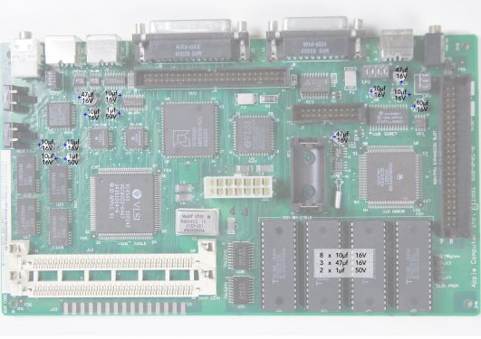 Macintosh Classic II (Rev A) Logic Board Recap Diagram
 -
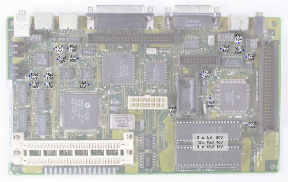 Macintosh Classic II (Rev B) Logic Board Recap Diagram
_recapping.jpg)
_Recapping.jpg)
Replacement Capacitor Recomendations
editTantalum Capacitors
Failure Mode: Tantalum caps can fail as a short circuit, especially if subjected to overvoltage, reverse polarity, or defects. A short can indeed pass unregulated voltage to downstream components (e.g., ICs), causing catastrophic damage. However, some tantalums are surge-robust (Kemet T495 up to 1.5x rated voltage) and have low failure rates when properly selected and installed.
Advantages:
- Extremely long lifespan (>200,000 hours at 40 °C)
- No electrolyte leakage
- Compact size
- Stable capacitance over time.
Risks:
- If installed incorrectly (e.g., reverse polarity) or if the power supply has significant spikes (common at Macs startup), a short could damage components. Overrating voltage (e.g., 35V instead of 25V) mitigates this risk significantly.
Solid Polymer Capacitors (Aluminum Polymer SMD)
Failure Mode: Aluminum polymer caps typically fail open or with high resistance, meaning they stop conducting rather than shorting. This is safer for vintage hardware, as an open failure prevents voltage from feeding directly into sensitive ICs, reducing the risk of collateral damage. Failures are rare and usually due to extreme overvoltage or mechanical stress, but polymers are more forgiving.
Advantages:
- Safer Failure Mode: Open failure minimizes risk to downstream components.
- Lower ESR: Typically 20–100 mΩ (vs. 200+ mΩ for T495 tantalums), improving stability and reducing heat.
- High Ripple Current: Handles power fluctuations well, ideal for power rails.
- Long Lifespan: 2,000–10,000 hours at 105 °C (translates to >50,000 hours at 40 °C), sufficient for vintage gear.
- No Leakage: Solid polymer electrolyte eliminates the corrosion issues of original wet aluminum electrolytic.
Disadvantages:
- Slightly larger footprints for high capacitance
- Shorter lifespan than tantalums at high temperatures (irrelevant for ~40 °C)
- Higher cost than standard aluminum electrolytics (0.50–2 €/piece).
Are Polymer Caps Safer?
Yes, due to open failure mode, which prevents shorts that could damage ICs. Low ESR and high ripple tolerance are excellent for power supply and filtering. Tantalums remain reliable when overrated and installed correctly, but the risk of a short-circuit failure makes polymers a better choice for vintage electronics. I recommend SMD Aluminum Polymer Capacitors from reputable brands (Nichicon, Panasonic, Rubycon) with slightly overrated voltage.
Below are recommended polymer capacitors, ensuring compatibility with the Classic II board (Rev.B) and all are SMD, RoHS, low ESR (20–100 mΩ).
- 1 µF 50V → 100V, ~4,5mm wide (1812 SMD) e.g. Kemet C1812Y105K1RACAUTO (Y-series short proof)
- 10 µF 16V → 20V, ~5mm wide e.g. Panasonic 20SVPA10M (5mm max width!)
- 47 µF 25V → 35V, ~6.3 mm wide e.g. Panasonic EEH-ZC1V470V I have done the recap with these caps, they are short proof, anti-leakage and it does work. My Classic II is alive again. For 10 µF 20V caps the 5mm diameter is the maximum width, so 25V do not fit, because soldering points are then under the cap. 20V on 12V rail is over dimensioned anyway and will last even longer than original 16V. Put solder on the pads, place the cap on the soldered pads and heat the pads with soldering iron and push down. The other caps are easy to solder.
Capacitor Replacement Procedure
edit- Discharge the CRT – Follow standard CRT discharge steps before opening the case.
- Remove the Boards – Label connectors; carefully extract the logic and analog boards.
- Desolder Old Caps – Use a temperature‑controlled iron with braid or pump for clean removal.
- Clean the PCB – Remove all electrolyte residue with 99 % IPA and an ESD‑safe brush.
- Install New Caps – Observe polarity (negative stripe); seat flush to the board.
- Solder Carefully – Aim for shiny, sloped joints; avoid cold bridges.
- Trim Leads & Inspect – Cut excess lead length and check with magnification.
- Test for Shorts – Verify with a multimeter across each power rail.
Recommended Tools
edit- Temperature‑controlled soldering iron (fine tip)
- Desoldering braid or vacuum pump
- Leaded solder, ~0.5 mm diameter
- 99 % isopropyl alcohol & ESD‑safe brush
- Multimeter
- Safety goggles & insulated gloves
Voltage Adjustment After Recap
editWith boards reinstalled, measure at the floppy‑drive power pins:
- +5 V rail: 4.90 – 5.15 V
- +12 V rail: 11.9 – 12.7 V
Use the analog board’s variable resistor (PP1) to fine‑tune.
Tips for Best Results
edit- Recap the logic board first—its leakage often damages the analog side.
- Use top‑tier caps (Nichicon, Panasonic, Rubycon).
- Power on the machine periodically after recap to “exercise” new caps.
- Replace complete sets for uniform aging and reliability.
- Always clean the board thoroughly post‑recap.
Related Pages
edit- Macintosh Classic / Classic II General Maintenance
- Macintosh Classic / Classic II Troubleshooting
- Macintosh Floppy Drive Maintenance
- CRT Discharge Procedure