

File:Sega Dreamcast VA0 block diagram.png
Size of this preview: 800 × 568 pixels. Other resolutions: 2,560 × 1,817 pixels | 3,722 × 2,642 pixels.

Original file (3,722 × 2,642 pixels, file size: 1.96 MB, MIME type: image/png)
Summary
[edit | edit source]

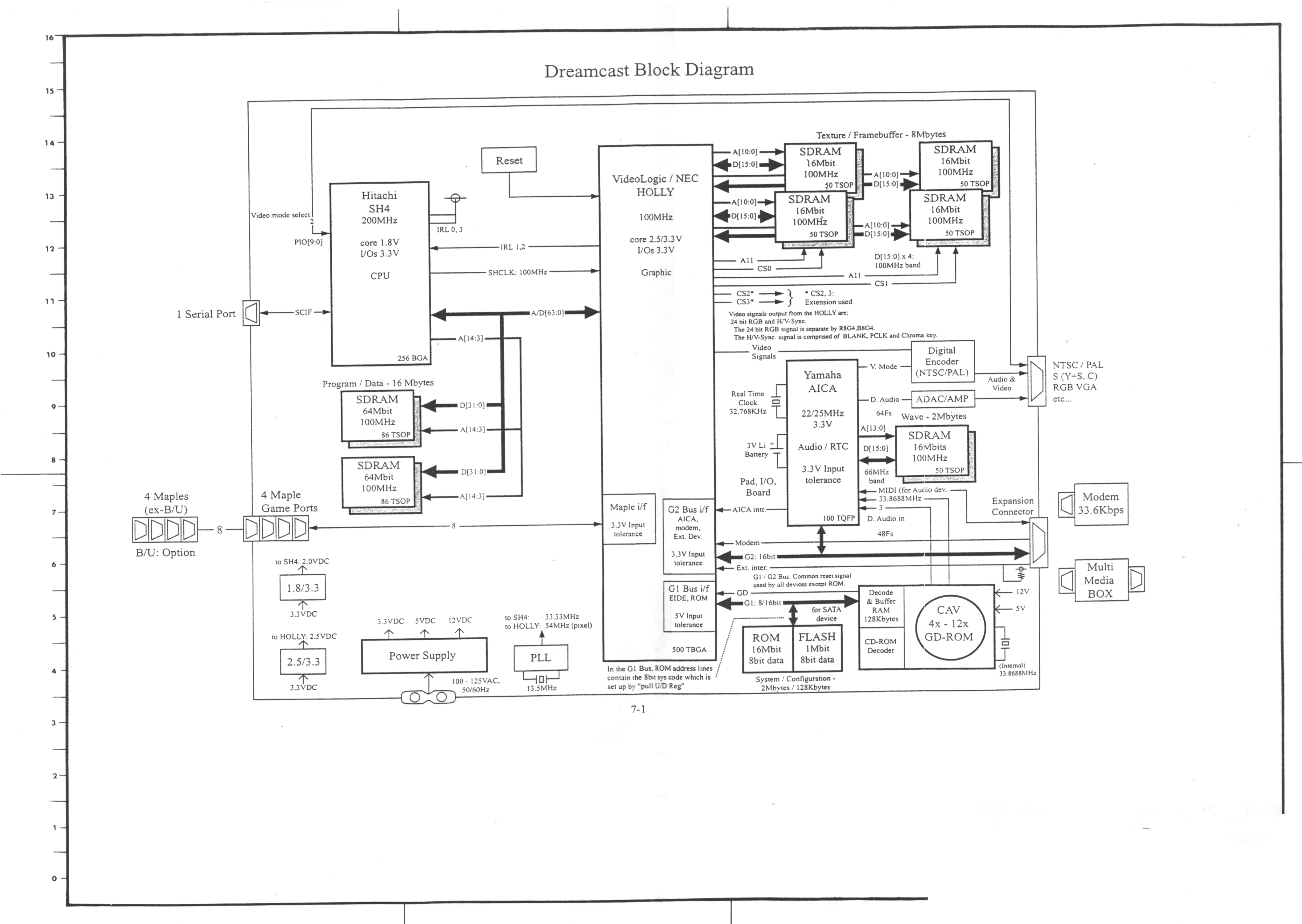
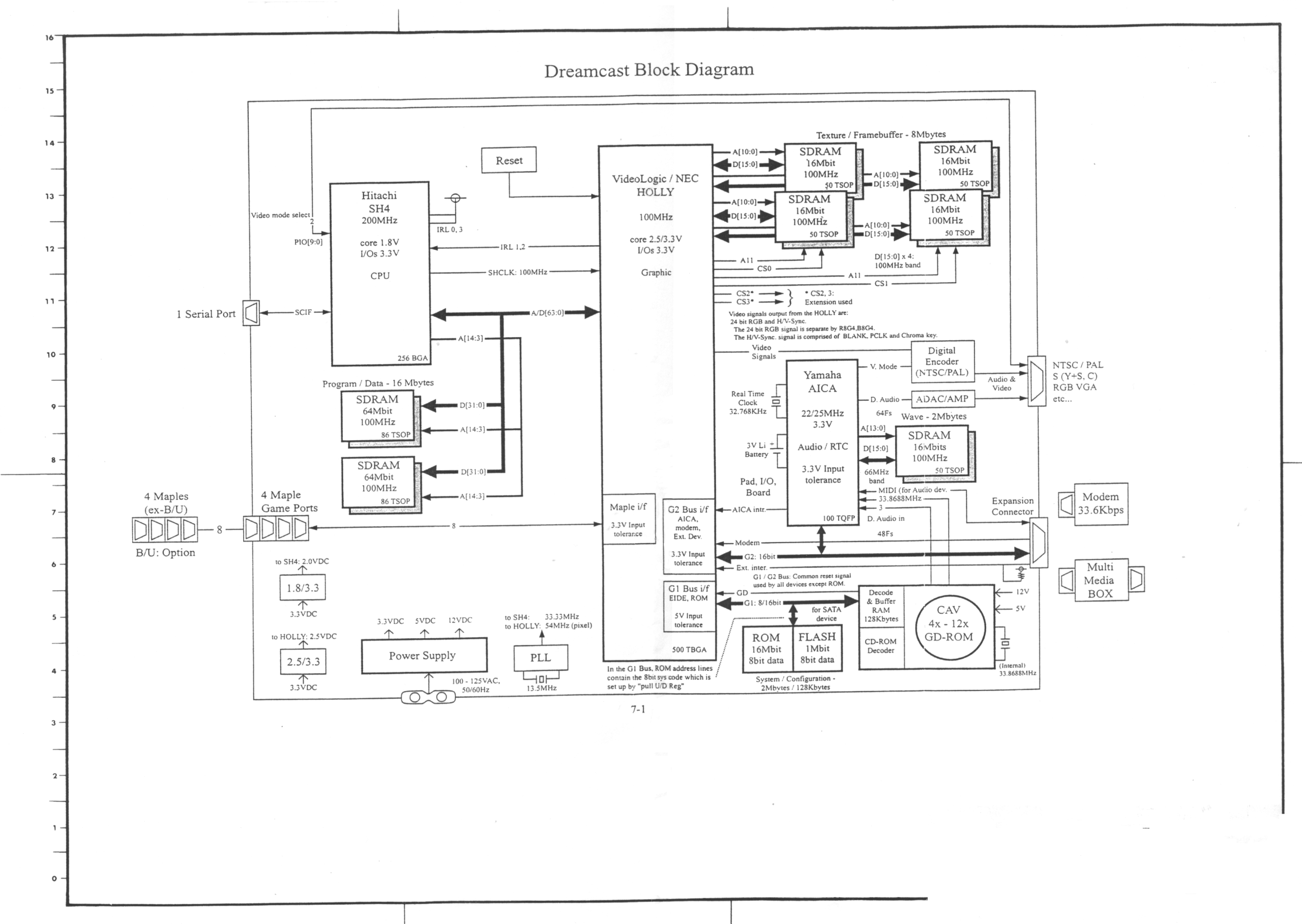
Sega's Dreamcast block diagram, service-manual sheet 7-1, as an image: the SH-4 and HOLLY, the memory banks, the G1, G2 and Maple buses, the GD-ROM drive, modem and expansion connector, and the power supply and core regulators. The PDF copy is File:Sega Dreamcast VA0 Block Diagram.pdf.
Source
[edit | edit source]

Extracted from File:Sega Dreamcast VA0 Block Diagram.pdf; see Sega Dreamcast VA0 Schematics.
Author
[edit | edit source]

Sega Enterprises, Ltd.
Licence
[edit | edit source]

Copyright Sega Enterprises, Ltd. Not freely licensed. Hosted for preservation and repair reference.
File history
Click on a date/time to view the file as it appeared at that time.
| Date/Time | Thumbnail | Dimensions | User | Comment | |
|---|---|---|---|---|---|
| current | 04:45, 23 September 2026 | | 3,722 × 2,642 (1.96 MB) | Josh (talk | contribs) | Sega Dreamcast block diagram sheet 7-1, extracted from the hosted PDF for inline display |
You cannot overwrite this file.
File usage
The following 2 pages use this file:
