

File:Amstrad CPC664 main PCB layout.jpg

Summary
[edit | edit source]

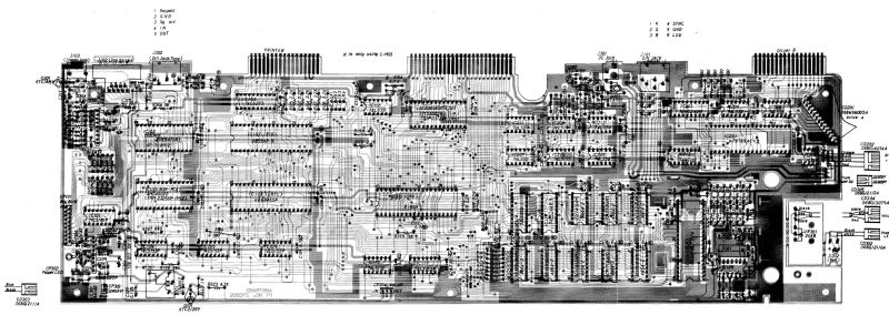
Component layout of the CPC664 main PCB (PCB101, MC0005B, marked PT NO Z70205), from pages 16–18 of Amstrad's CPC664 service manual. The 300-series audio and cassette-interface parts, including most of the board's electrolytic capacitors, are at the left-hand end. Cropped and reduced from the scan.
Source
[edit | edit source]

Amstrad Consumer Electronics plc, CPC664 Micro Computer / CTM644 Colour Monitor / GT65 Green Monitor Service Manual, pp. 16–18 "CPC664 Main PCB". Rendered from File:Amstrad CPC664 Service Manual.pdf (described at Amstrad CPC 664 Service Manual), 2026-10-01.
Author
[edit | edit source]

Amstrad Consumer Electronics plc
Licence
[edit | edit source]

Copyright Amstrad. Reproduced from the service manual for preservation and repair reference.
File history
Click on a date/time to view the file as it appeared at that time.
| Date/Time | Thumbnail | Dimensions | User | Comment | |
|---|---|---|---|---|---|
| current | 09:01, 1 October 2026 | | 3,424 × 1,216 (1.58 MB) | Josh (talk | contribs) | Main PCB layout from the CPC664 service manual, pp. 16-18 |
You cannot overwrite this file.
File usage
The following 2 pages use this file:
