

File:Apple Data Modem 2400 main logic board removal (Apple Technical Procedures).png

Summary
[edit | edit source].png&veaction=edit§ion=1)
.png&action=edit§ion=1)
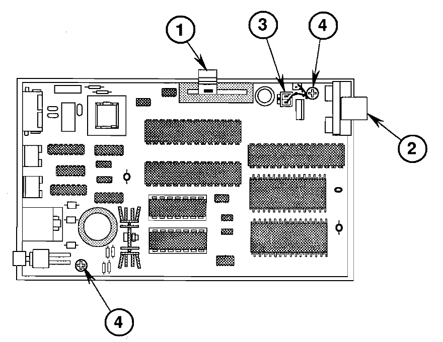
Apple's drawing of the Apple Data Modem 2400 main logic board in the bottom case, with callouts for (1) the volume lever, (2) the light pipe assembly, (3) the speaker cable and (4) the two mounting screws (Figure 7, p. 3.11 of the Modems tab of Apple Service Technical Procedures: Cross Family Peripherals, Volume One, Aug 1989 page). Cropped from a 200 dpi render of the page.
Source
[edit | edit source].png&veaction=edit§ion=2)
.png&action=edit§ion=2)
File:Apple Technical Procedures Modems (1991).pdf, from the archive.org item Apple_Service_Technical_Procedures_Cross_Family_Peripherals_Volume_1_April_1991 (retrieved 2026-10-02).
Author
[edit | edit source].png&veaction=edit§ion=3)
.png&action=edit§ion=3)
Apple Computer, Inc.
Licence
[edit | edit source].png&veaction=edit§ion=4)
.png&action=edit§ion=4)
Copyright Apple Computer, Inc. Manufacturer drawing used for repair reference.
File history
Click on a date/time to view the file as it appeared at that time.
| Date/Time | Thumbnail | Dimensions | User | Comment | |
|---|---|---|---|---|---|
| current | 12:51, 4 October 2026 | | 880 × 680 (30 KB) | Josh (talk | contribs) | Upload Apple modem service documentation |
You cannot overwrite this file.
File usage
The following page uses this file:
.png&oldid=23507)