

File:Atari 835 power supply schematic (field service manual).png
Size of this preview: 800 × 309 pixels. Other resolution: 2,041 × 788 pixels.

Original file (2,041 × 788 pixels, file size: 74 KB, MIME type: image/png)
Summary
[edit | edit source].png&veaction=edit§ion=1)
.png&action=edit§ion=1)
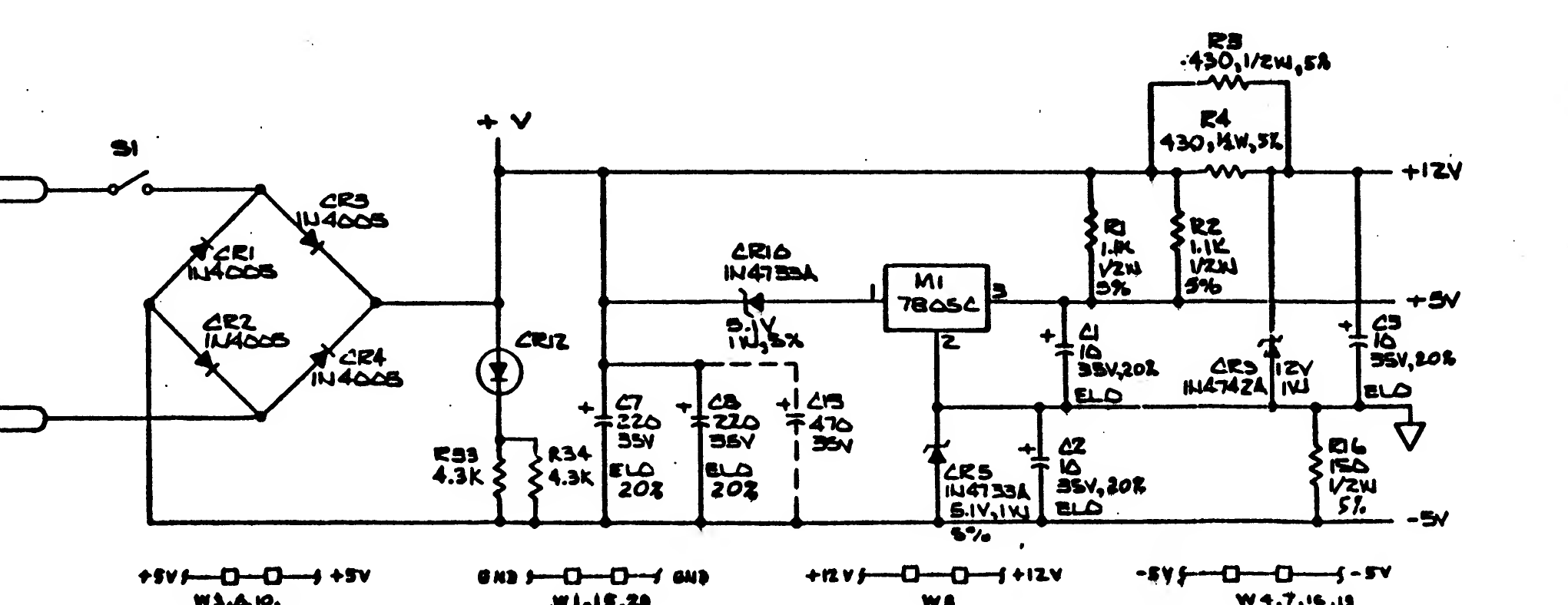
Power supply section of the Atari 835 Direct Connect Modem schematic (page 2 of the drawing package in field service manual FD100268 Rev. 01): bridge rectifier CR1 to CR4, power LED CR12, filter capacitors C7, C8 and the dashed C13, regulator M1 (7805C), and the +12 V, +5 V and -5 V rails with C1, C2 and C3.
Source
[edit | edit source].png&veaction=edit§ion=2)
.png&action=edit§ion=2)
Rendered at 300 dpi from File:Atari 835 Direct Connect Modem Field Service Manual FD100268 Rev 01.pdf, page 40 of the PDF, cropped and converted to greyscale, 2026-10-04.
Author
[edit | edit source].png&veaction=edit§ion=3)
.png&action=edit§ion=3)
Atari, Inc.
Licence
[edit | edit source].png&veaction=edit§ion=4)
.png&action=edit§ion=4)
Copyright Atari, Inc. Reproduced from the service manual for repair reference.
File history
Click on a date/time to view the file as it appeared at that time.
| Date/Time | Thumbnail | Dimensions | User | Comment | |
|---|---|---|---|---|---|
| current | 15:23, 4 October 2026 | | 2,041 × 788 (74 KB) | Josh (talk | contribs) | Upload image with source and licence |
You cannot overwrite this file.
File usage
The following 2 pages use this file:
.png&oldid=24103)