

Atari 835
| Atari 835 Direct Connect Modem | |
|---|---|
 |
|
| The 835, from Atari's Communicator II set-up leaflet | |
| Manufacturer | Racal-Vadic, for Atari, Inc. |
| Type | Direct-connect modem |
| Release date | Announced June 1982 in The Communicator II kit[1] |
| Interface | Atari SIO, two 13-pin I/O connectors; RJ11 line and telephone jacks[1] |
| Compatible | Atari 400, Atari 800 and Atari 1200XL[2] |
| Power | External adaptor, 22 V AC (Atari C060479, boxed as CA060535)[2][1] |
The Atari 835 Direct Connect Modem is a 300 bit/s Bell 103 modem that plugs straight into the telephone line and into the Atari 8-bit computer's serial I/O (SIO) bus, with no interface module. It dials by pulses under software control, switches between originate and answer mode by command, and can pass the line audio to the television speaker.[2] Atari sold it only in The Communicator II kit (CX488), with the TeleLink II cartridge, announced at the Summer Consumer Electronics Show in June 1982.[1] It was made for Atari by Racal-Vadic.[1]
Hardware
[edit | edit source]| Position | Device | Part number |
|---|---|---|
| M5 | Intel 8048 controller with Atari firmware | C060549 |
| M4 | Texas Instruments 99532 FSK modem chip | FC100279 |
| M6 | LM339 comparator (SIO input buffer) | FC100281 |
| M2 | 4558 dual op amp (line interface) | FC100278 |
| M3 | 4053 multiplexer | FC100280 |
| M1 | 7805C regulator (schematic) | Not in the parts list |
| K1 | Hook relay | FC100284 |
| T1 | 600 Ω line transformer | FC100283 |
| Y1 | 4.032 MHz crystal | FC100282 |
The 8048 translates the computer's commands, passes data to and from the modem chip, drives the hook relay for going off-hook and for pulse dialling, sets originate or answer mode, controls the audio monitor, and tests itself and the modem chip at power-up. It talks to the computer with the normal SIO protocol at 300 baud.[2] In originate mode the modem chip sends 1,270 Hz for a mark and 1,070 Hz for a space; in answer mode it sends 2,225 Hz and 2,025 Hz.[2]
The power supply takes 22 V AC from the adaptor and makes about +18 V (+V) for the hook relay and carrier LED drivers, +12 V for the modem chip, +5 V for the rest of the board, and -5 V for the hook relay driver and the modem chip.[2] The modem has a power LED and an ON-LINE light; at switch-on the ON-LINE light flashes once and goes out when the self-test passes.[2][3]
Connecting
[edit | edit source]Atari's set-up leaflet connects the 835 between the wall jack (LINE) and the telephone (TELEPHONE), and to the computer with an SIO cable; an Atari 820 or Atari 822 printer can plug into the modem's other SIO port. An Atari 810 can stay connected as long as it is not switched on while the modem is in use. Users had to tell the telephone company the model, the FCC registration number and the ringer equivalence from the label underneath.[3]
Atari warns against connecting the 835 to Bell's "Horizon" system, a four-wire installation that accepts only touch-tone dialling, because doing so damages the telephone system.[2] The 835 dials by pulses only.[1]
Known faults
[edit | edit source]Atari's flowcharts trace most faults to a few parts: the adaptor or bridge rectifier (no power LED), the modem chip M4 or controller M5 (ON-LINE light keeps flashing), the hook relay K1 and its driver transistor Q1, and the multiplexer M3 and op amp M2 in the audio and transmit path.[2] The Atari 835 Troubleshooting guide follows them step by step, and the Atari 835 Capacitor Replacement Guide lists the electrolytics.
Documentation
[edit | edit source]- Atari 835 Documentation: the field service manual and the Communicator II leaflet.
- 835 Direct Connect Modem Field Service Manual (FD100268 Rev. 01, 1983)
- The Communicator II: Getting Started (C024438-001 Rev. A)
Gallery
[edit | edit source]-
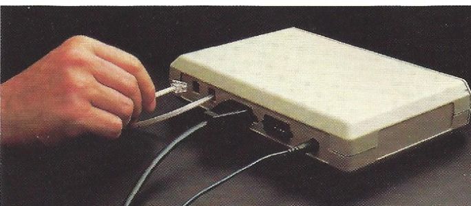 Rear of the 835 with cables being connected
-
 Power supply section of the schematic (FD100268)


Related pages
[edit | edit source]- Atari 835 Troubleshooting
- Atari 835 Capacitor Replacement Guide
- Atari 835 Documentation
- Atari 830
- Atari 1030
References
[edit | edit source]- ↑ 1.0 1.1 1.2 1.3 1.4 1.5 Michael D. Current (ed.), Atari 8-Bit Computers: Frequently Asked Questions, comp.sys.atari.8bit FAQ, last modified 2 August 2026: section 5.1.1 (the Atari 835 modem), section 6.2 (power requirements), section 6.4 (The Communicator II kit CX488) and section 11.1 (history, 1982). mcurrent.name. Community reference.
- ↑ 2.0 2.1 2.2 2.3 2.4 2.5 2.6 2.7 2.8 Atari, Inc., 835 Direct Connect Modem Field Service Manual (FD100268, Rev. 01, March 1983): theory of operation pp. 1-1 to 1-5; schematic and silkscreen (oversize sheets); test procedures pp. 3-1 to 3-3; diagnostic flowchart pp. 4-1 to 4-13; parts list p. 5-1. Hosted here as File:Atari 835 Direct Connect Modem Field Service Manual FD100268 Rev 01.pdf.
- ↑ 3.0 3.1 Atari, Inc., The Communicator II: Getting Started (C024438-001 Rev. A), set-up steps 1 to 10. Hosted here as File:The Communicator II Getting Started C024438-001.pdf.