

Atari 1050
| Atari 1050 | |
|---|---|
 |
|
| Atari 1050 disk drive | |
| Manufacturer | Atari, Inc.; later Atari Corporation |
| Type | 5.25-inch floppy disk drive |
| Release date | Announced June 1983; shipping from summer 1983[1] |
| Interface | Atari SIO, two 13-pin I/O connectors[2] |
| Compatible | Atari 8-bit computers with at least 16 KB of RAM[2] |
| Power | External 9 V AC adaptor (Atari 31 VA, C017945)[2][1] |
| Storage | 92,160 bytes formatted in single density; 133,120 bytes in dual density[2] |
| Media | Single-sided 5.25-inch diskettes, 40 tracks[2] |
The Atari 1050 is a single-sided 5.25-inch floppy disk drive for the Atari 8-bit computers. Atari announced it at the Summer Consumer Electronics Show in June 1983 alongside the 600XL and 800XL, and began shipping it that summer with DOS 2.0S.[1] It replaced the Atari 810, reading and writing the 810's single-density format and adding a dual-density (Atari also called it enhanced density) format of 26 sectors per track.[1][2]
Atari's field service manual, FD100330, is the source for most of the hardware detail below. It describes the version built with a Tandon TM50-1 mechanism.[2]
History
[edit | edit source]Atari introduced the 1050 at the June 1983 Summer CES with "DOS III", and shipped the first drives in summer 1983 with DOS II version 2.0S, which cannot use the dual-density format. DOS 3 replaced 2.0S in the box during the winter of 1983-84, and DOS 2.5 replaced DOS 3 in spring 1985.[1] In January 1985 Atari announced a US$399 130XE bundle that included a 1027 printer and a 1050 drive.[1]
The first 1,700 drives shipped with firmware revision E or F in the ROM at U10. That firmware returned a different error status from the 810 when it met some copy-protection schemes, so some third-party software would not boot. Atari's Tech Tip 21 of 30 September 1983 told service centres to replace the EPROM with FC100541 Rev. 1.[2]
The successor was the Atari XF551 of 1987, which added true double density and double-sided operation.[3]
Specifications
[edit | edit source]| Single density | Dual density | |
|---|---|---|
| Encoding | FM | MFM |
| Tracks per surface | 40 | 40 |
| Tracks per inch | 48 | 48 |
| Sectors per track | 18 | 26 |
| Bytes per sector | 128 | 128 |
| Formatted capacity | 92,160 bytes | 133,120 bytes |
| Unformatted capacity per surface | 135,280 bytes | 260,400 bytes |
| Disk transfer rate | 125,000 bit/s | 250,000 bit/s |
| Rotational speed | 288 rpm ±3 % | 288 rpm ±3 % |
| Track-to-track access (maximum) | 40 ms | 40 ms |
| Head settling (maximum) | 30 ms | 30 ms |
| Motor start (maximum) | 1,000 ms | 1,000 ms |
The dual-density format keeps 128-byte sectors, so it is not the 180 KB double density (18 sectors of 256 bytes) used by the Atari 815 and by most third-party drives.[1] The link to the computer runs at 19.2 kbit/s.[1] The drive firmware supports the Get Sector, Put Sector, Put Sector with Verify, Status Request and Format Disk commands.[2]
Atari specifies an input of 8.52 V AC ±12 % at 60 ±3 Hz, and a power consumption of 15 W in standby, 30 W operating and 50 W at start-up (maximum figures).[2]
Hardware
[edit | edit source]All of the logic and analogue circuitry is on one board under the drive mechanism. The board carries a 6507 processor, a 6810 RAM, a 2732 ROM holding the drive firmware, a 6532 PIA and a WD2793 floppy disk controller, clocked from a 4 MHz crystal.[2] The five LSI chips sit under an RF shield held on by bent tabs.[2]
| Position | Device | Atari part number | Function |
|---|---|---|---|
| U7 | 6532 | C010750 | PIA: serial interface, stepper phases, motor and switches |
| U8 | 6810 (1 MHz) | C014328 | RAM |
| U9 | 6507 (1 MHz) | C010745 | Microprocessor |
| U10 | 2732, custom | FC100541 | Firmware ROM |
| U13 | WD2793-02 | FC100542 | Floppy disk controller |
| U5 | LM2917 | C017101 | Frequency-to-voltage converter in the spindle speed loop |
| U1, U21 | LM3086 | C016821 | Transistor arrays (U1 on the serial bus, U21 in the write circuit) |
| U2, U3 | 75478 | FC100536 | Stepper motor drivers |
| Y1 | 4 MHz crystal | FC100534 | Clock |
The function column follows the service manual's theory of operation and the Sams schematic, which labels U21 the write amplifier, U1 the serial-port amplifier and U5 the frequency-to-voltage converter.[2][4] The Sams sample used different but equivalent parts in some positions: a CS2719 at U5, UDN5713M drivers at U2 and U3, and BY251 rectifiers where Atari lists MR501.[4][2]
Power supply
[edit | edit source]The adaptor steps 120 V AC down to 9 V AC and has an internal 2 A fuse. On the board the power switch feeds a bridge rectifier (CR17-CR20). A regulator (Q7) makes +5 V for the logic and the controller, and a voltage doubler (CR15, CR16, C71) feeds a second regulator (Q8) that makes +12 V for the stepper motor, spindle motor, read/write and erase circuits and the tachometer feedback.[2] Atari's schematic shows 7805 and 7812 regulators, 1N4001 doubler diodes and three 4,700 µF 35 V filter capacitors; the Sams sample had a µA7805, an L7812CV, 1N5392 doubler diodes and 6,800 µF capacitors at C68 and C71.[2][4] Test point TP13 is +5 V, TP14 is +12 V and TP15 is ground.[2]
The 1050 runs on AC. An Indus GT supply is DC, and plugging one into a 1050 usually blows the rectifier diodes.[1]
Drive mechanism
[edit | edit source]The mechanism carries the spindle motor, the stepper motor, the head carriage, the write protect sensor, the track 00 sensor and the diskette enable switch. The spindle motor is a DC motor with an internal tachometer, and drives the disk through a belt and flywheel; the stepper is a four-phase motor driven by four PIA lines.[2] Atari's parts list covers the Tandon TM50-1 mechanism (FA100514).[2] Drives were also built with World Storage Technology mechanisms, which use different parts, including a track 00 sensor in a different package.[5]
Drive number
[edit | edit source]A two-position switch block behind a window at the rear sets the drive number. With both the black and the white switch to the left the drive is drive 1; black right and white left gives drive 2; black left and white right gives drive 3; both right gives drive 4.[1][6] One drive in the system must be set to drive 1.[6]
Upgrades
[edit | edit source]Several third-party boards gave the 1050 true 180 KB double density and faster transfer, among them the ICD US Doubler, the Happy 1050 and the Speedy 1050.[1] Atari's diagnostic diskette does not work with a drive fitted with a Happy or Speedy board, and fails the same tests that an out-of-speed drive fails.[7]
Known faults
[edit | edit source]- Spindle speed drifts. Atari sets it with VR2 to 208.3 ms per revolution, which is 288 rpm.[2]
- The track 00 sensor fails or moves, and the head steps outwards against its stop at power-on.[5]
- Plugging or unplugging the SIO cable with the power pack connected can destroy the LM3086 array at U1.[1]
- Bad 6810 RAM at U8 leaves the drive dead with no activity light.[8]
Diagnosis is covered in the Atari 1050 Drive Troubleshooting guide, routine care and adjustments in the Atari 1050 Maintenance Guide, and the electrolytic capacitors in the Atari 1050 Capacitor Replacement Guide.
Documentation
[edit | edit source]- Atari 1050 Documentation: the field service manual, the Sams Computerfacts and the owner's guide, with contents and notes.
- Atari 1050 Disk Drive Field Service Manual (FD100330)
- Sams Computerfacts CD13, Atari Model 1050 Disk Drive (1987)
- Atari 1050 Disk Drive Owner's Guide (1982)
Gallery
[edit | edit source]-
 Top cover removed, showing the mechanism over the main board
 -
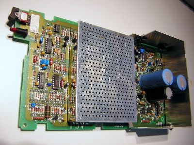 Main board out of the case
 -
 Adjustment points on the Tandon mechanism (FD100330 figure 2-2)


.png)
Related pages
[edit | edit source]- Atari 1050 Maintenance Guide
- Atari 1050 Drive Troubleshooting
- Atari 1050 Capacitor Replacement Guide
- Atari 1050 Documentation
- Floppy Drive Repair
- Atari 800XL
References
[edit | edit source]- ↑ 1.00 1.01 1.02 1.03 1.04 1.05 1.06 1.07 1.08 1.09 1.10 1.11 Michael D. Current (ed.), Atari 8-Bit Computers: Frequently Asked Questions, comp.sys.atari.8bit FAQ, last modified 29 November 2009: section 3.4 (the 810, 815, 1050 and XF551 drives, drive select switches, third-party upgrades, the U1 failure note), section 6.7 (power requirements) and section 11.1 (history, 1983 to 1985). faqs.org. Community reference.
- ↑ 2.00 2.01 2.02 2.03 2.04 2.05 2.06 2.07 2.08 2.09 2.10 2.11 2.12 2.13 2.14 2.15 2.16 2.17 2.18 2.19 Atari, Inc., 1050 Disk Drive Field Service Manual (FD100330; Rev. 03 is dated October 1985). Section 1, theory of operation (overview p. 1-1, power supply p. 1-8, serial bus pp. 1-20 and 1-21); Section 2, test equipment and diagnostic tests (pp. 2-1 to 2-11); Section 3, disassembly (pp. 3-1 and 3-2); Section 4, symptom checklist (pp. 4-1 to 4-7); Section 5, parts list (p. 5-11); Appendix 6A, specifications (pp. 6A-1 to 6A-3); Tech Tip 21. Hosted here as File:Atari 1050 Disk Drive Field Service Manual.pdf.
- ↑ Wikipedia, "Atari 1050". en.wikipedia.org. Used for release history only.
- ↑ 4.0 4.1 4.2 Howard W. Sams & Co., Computerfacts CD13, Atari Model 1050 Disk Drive (1987): schematic with voltages and waveforms, parts list p. 9. Hosted here as File:Sams Computerfacts CD13 Atari 1050 Disk Drive.pdf.
- ↑ 5.0 5.1 "Atari 1050 Track 0 sensor repair", AtariAge Forums, Atari 8-Bit Computers, thread started by TGB1718, 8 February 2019, with replies by tep392 and kheller2 (22 August 2022). forums.atariage.com. Community repair report.
- ↑ 6.0 6.1 Atari, Inc., Atari 1050 Disk Drive Owner's Guide (1982), connecting and drive select pages. Hosted here as File:Atari 1050 Disk Drive Owner's Guide.pdf.
- ↑ Jason H. Moore, "Diagnose and Fix an Atari 1050 Disk Drive (30-60 mins)", Atari Projects, 8 August 2021. atariprojects.org. Community repair write-up.
- ↑ "Attempting to repair a 1050 Disk Drive - no activity light no motor/head spin", AtariAge Forums, Atari 8-Bit Computers, thread started by repetto74, 4-5 September 2018, with replies by Nezgar and xrbrevin. forums.atariage.com. Community repair report.