

Atari XF551
| Atari XF551 Disk Drive | |
|---|---|
 |
|
| Atari XF551 (Mitsumi-mechanism version) | |
| Manufacturer | Atari Corporation; drive mechanism by Mitsumi or Chinon[1] |
| Type | 5.25-inch floppy disk drive |
| Release date | Shown June 1987; shipped December 1987[1][2] |
| Price | US$199.95 (1988)[3] |
| Interface | Atari SIO, two sockets[1] |
| Compatible | Atari 400, Atari 800, XL and XE computers |
| Dimensions | 70 × 180 × 290 mm[4] |
| Weight | 2.7 kg[4][3] |
| Predecessor | Atari 1050[1] |
| Power | 9 V AC from an external adaptor (Atari CA017964 or equivalent)[1] |
| Storage | 90 KB, 130 KB, 180 KB or 360 KB per disk, by mode[1] |
| Media | 5.25-inch diskettes, single or double sided |
The Atari XF551 is a 5.25-inch floppy disk drive for the Atari 8-bit computers, introduced by Atari Corporation in June 1987 as the replacement for the Atari 1050. It reads and writes the single-density format of the Atari 810 and the enhanced density of the 1050, and adds true double density (180 KB per side) and, with a second head, a double-sided mode of 360 KB per disk.[1] It was the last disk drive Atari made for the 400/800, XL and XE computers.[5]
History
[edit | edit source]Atari introduced the XF551 at the Summer Consumer Electronics Show in Chicago (30 May to 2 June 1987), with the new DOS then called ADOS. The drive shipped towards the end of 1987 with DOS 2.5; DOS XE, the renamed ADOS, replaced DOS 2.5 in the box from January 1989.[1][2] Jose Valdes was the drive's key engineer at Atari.[1]
Antic reviewed the drive in June 1988, when it had "finally reached the market" at the same US$199.95 list price as the 1050. The reviewer found it much quieter than the 810 and 1050, noted the missing power light and the power switch at the rear, and measured it about 12.5 % faster than a 1050 on an 8 KB file under SmartDOS.[3] The review also reported a 6507 processor inside; the FAQ notes that early Atari and press reports were wrong about this, and Atari's schematic shows an 8040 microcontroller.[3][1][6] The Atari Computermuseum lists the PCF554, a drive for Atari's PC range, as a sister model with the same case and mechanism.[2]
Specifications
[edit | edit source]| Mode | Encoding | Sides | Tracks | Sectors per track | Bytes per sector | Capacity |
|---|---|---|---|---|---|---|
| Single density | FM | 1 | 40 | 18 | 128 | 92,160 bytes |
| Enhanced ("dual") density | MFM | 1 | 40 | 26 | 128 | 133,120 bytes |
| Double density | MFM | 1 | 40 | 18 | 256 | 184,320 bytes |
| Double-sided double density | MFM | 2 | 80 | 18 | 256 | 368,640 bytes |
The XF551 spins at 300 rpm. Its normal SIO rate is 19,040 bit/s on NTSC computers and 18,688 bit/s on PAL; in double-sided double-density mode it can also transfer at about twice that (38,908 and 38,553 bit/s), with DOS XE, SpartaDOS X and other operating systems that support it.[1] In double-sided mode it fills the first side from the outside in and then the second side from the inside out, so double-sided disks written by drives that use another layout are not compatible.[1]
The front has a busy light but no power light. The rear has the power switch, the power socket, two SIO sockets and two drive select switches.[1][3]
| Drive | Left switch | Right switch |
|---|---|---|
| 1 | Down | Down |
| 2 | Down | Up |
| 3 | Up | Down |
| 4 | Up | Up |
The settings are from the FAQ.[1] Atari's schematic shows the same four combinations of S2-1 and S2-2.[6]
Versions
[edit | edit source]Both versions were made in Japan. The busy light and the shape of the door latch tell them apart.[1]
| Mitsumi | Chinon (FZ-502 mechanism) | |
|---|---|---|
| Production | Most units; earlier | Uncommon; late |
| Busy light | Rectangular, green, below the latch | Round, red, to the left of the latch |
| Opening the latch | Disk stays in place | Disk is ejected |
| Inserting a disk | No drive activity | Motor spins briefly and the light flashes |
| Reverse side of a "flippy" disk in single-sided modes | Reads and writes without a second index hole | Needs a second index hole |
| Formatting the reverse side | Needs a second index hole | Needs a second index hole |
Igor Gramblička identifies the Mitsumi mechanism as the D503V.[7]
.png)
Hardware
[edit | edit source]The controller board is built round an Intel 8040 or 8050 microcontroller running 4 KB of firmware, and a Western Digital WD1772 floppy disk controller; late units use the WD1770. The firmware is in a separate ROM on every 8040 board and most 8050 boards, and inside the 8050 on some.[1] Atari's schematic C100727 shows the 8040 (U1) and WD1772-02 (U2) clocked from an 8.333 MHz oscillator, with a 74LS38 (U3) and 74LS14 (U4) as glue. 2N3904 transistors Q1 to Q3 buffer the SIO data-out and command lines, and a 74LS38 gate drives the data-in line.[6] A jumper on pin 7 of U1 selects external or internal program memory. Gramblička points out that the schematic labels this jumper wrongly: pin 7 goes to ground for an 8040, or an 8050 using the external EPROM, and to +5 V for an 8050 running its internal firmware.[8] The drive mechanism connects through the usual 34-way floppy interface (J4) and a four-way power connector (J5).[6][3]
Gramblička, who has repaired a number of these drives, reports that:[7]
- the firmware sits in a 2764 EPROM (8 KB) of which only 4 KB is used, so a 2732 can be fitted in the socket offset by two pins;
- the 8.333 MHz clock, 4 % faster than 8 MHz, matches the 4 % difference between the XF551's 300 rpm and the 288 rpm of Atari's earlier drives;
- the board is single-sided, on a paper-based laminate, with many wire links;
- boards exist with duplicated component designators and with the ON and OFF markings of the power switch transposed.
He also describes two board versions, from 1987 and 1988, which differ in the power supply and in the use of the 74LS14 gates; the later board drops some of the extra DC filtering.[8]
Power supply
[edit | edit source].png)
The XF551 takes 9 V AC from an external adaptor, the same 31 VA unit used with the 810 and 1050 (Atari C017945, sold as CA017964).[1][3] On the board, the AC passes the power switch S1 and a filter choke L1 to the bridge rectifier D1. The DC from the bridge feeds the +5 V regulator Q5 through the 4700 µF reservoir C103. A voltage doubler (C102, D2 and D3) charges C104 and feeds the 7812 +12 V regulator Q6. Both rails go to the drive mechanism through J5: +5 V on pin 1 and +12 V on pin 4, with ground on pins 2 and 3. Test point TP14 is on the +12 V output.[6]
Gramblička gives the input of the 7805 as about 14 V DC and the input of the 7812 as about 23 to 26 V; the regulators drop the difference as heat on their heatsink.[9][7] The Maintenance Guide covers what that heat does to the drive.
Firmware and DOS
[edit | edit source]The XF551 shipped with DOS 2.5, which uses only the 810 and 1050 densities, and from January 1989 with DOS XE, which supports the double-sided mode and the high-speed transfers.[1][3] Gramblička reports that the early firmware came in separate NTSC and PAL versions with slightly different transfer rates, that version 7.7 works with both, and that version 7.7 does not detect a change of density when another disk is inserted. Bob Woolley's patched 7.7p, a 23-byte change, fixes the density detection without any hardware change.[7]
Upgrades
[edit | edit source]| Upgrade | Maker and date | What it does |
|---|---|---|
| XF35 Kit | Innovative Concepts, 1988 (Bob Woolley) | Replacement ROM so a standard 3.5-inch 720 KB mechanism can replace or join the 5.25-inch drive |
| XF Single Drive and XF Dual Drive Upgrade | Computer Software Services, 1991 | 3.5-inch drive in place of, or beside, the 5.25-inch drive; reads 3.5-inch MS-DOS disks |
| XF551 Enhancer | Computer Software Services | Switch to read, write and format the reverse side of a disk with one index hole |
| XF Update | Computer Software Services, 1992 | Replacement drive ROM with UltraSpeed and better density changes |
| XF Speedy | Klaus Peters, 1994 | Replaces the 8040 with a 65C02, ROM and memory; Speedy 1050 compatibility |
| Hyper-XF | Stefan Dorndorf, 1998 | Replacement ROM for 5.25-inch or 3.5-inch drives, with UltraSpeed and partitions |
| Reimaged XF551 controller | Bits of the Past, 2014 | New controller board |
The table is condensed from the FAQ.[1] Gramblička notes that Hyper-XF needs an extra microswitch on the mechanism so the drive knows when a disk has been inserted, and that the XF Speedy stacks two boards in the processor socket and does not work in every XF551.[7][10]
Known faults
[edit | edit source]The faults reported most often are broken solder joints at the SIO sockets, a loose head shield on the Mitsumi mechanism, overheating of the regulators, worn power switches and corrupted EPROMs.[7][11] Some commercial disks, among them Flight Simulator II and Blue Max, do not load on the XF551 because of its 300 rpm speed.[12] The diagnosis and repair of each is on the Atari XF551 Drive Troubleshooting page; routine care is on the Atari XF551 Maintenance Guide, and the electrolytics are listed on the Atari XF551 Capacitor Replacement Guide.
Documentation
[edit | edit source]- Atari XF551 Documentation: Atari's schematic and the owner's manual, with contents.
- Schematic Diagram XF551 (FCC), Atari (Japan) Corporation drawing C100727 rev. 1, sheet 1 of 2, preliminary release, November 1987.
- Atari DOS 2.5: XF551 Disk Drive Owner's Manual, C033537-001, 1987.
Gallery
[edit | edit source]-
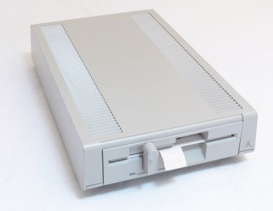 Mitsumi version, rectangular busy light below the latch
 -
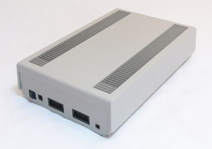 Rear: power switch, power socket, two SIO sockets and drive select switches
.jpg)
Related pages
[edit | edit source]- Atari XF551 Maintenance Guide
- Atari XF551 Drive Troubleshooting
- Atari XF551 Capacitor Replacement Guide
- Atari XF551 Documentation
- Atari 1050
- Atari 810
- Floppy Drive Repair
References
[edit | edit source]- ↑ 1.00 1.01 1.02 1.03 1.04 1.05 1.06 1.07 1.08 1.09 1.10 1.11 1.12 1.13 1.14 1.15 1.16 1.17 1.18 Michael D. Current (ed.), Atari 8-Bit Computers: Frequently Asked Questions, last modified 2 August 2026, mcurrent.name (retrieved 2026-10-06). Section 3.2.3 (the XF551: modes, rotation, SIO rates, microcontrollers, FDC, versions, switches, power, manuals, designer, upgrades), section 6.2 (power supplies: C017945/CA017964, 9 V AC 31 VA, for use with the XF551) and the 1987 and 1989 chronology in section 11.1. Community reference.
- ↑ 2.0 2.1 2.2 Atari Computermuseum, "XE-Peripherie: Atari XF551 Disk Drive", atari-computermuseum.de (retrieved 2026-10-06), in German. Presentation at the Summer CES on 30 May 1987, on sale December 1987 with DOS 2.5 and January 1989 with DOS XE, sister model PCF554.
- ↑ 3.0 3.1 3.2 3.3 3.4 3.5 3.6 3.7 Rich Tietjens, "Atari's New Super Disk Drive: First look inside the XF551", Antic vol. 7 no. 2, June 1988, atarimagazines.com (retrieved 2026-10-06). Price, size and weight, controls, power supply, speed tests.
- ↑ 4.0 4.1 Atari Corporation, Atari DOS 2.5: XF551 Disk Drive Owner's Manual, C033537-001, 1987. Section 1, pp. 1–5 (connecting, drive select switches, care of diskettes); Appendix M, p. 141 (dimensions and weight). Hosted as File:Atari DOS 2.5 XF551 Disk Drive Owner's Manual C033537.pdf.
- ↑ Curt Vendel, "The Atari XF551", Atari Museum, XE peripherals section, updated 23 March 2020, atarimuseum.ctrl-alt-rees.com (retrieved 2026-10-06).
- ↑ 6.0 6.1 6.2 6.3 6.4 Atari (Japan) Corporation, Schematic Diagram XF551 (FCC), drawing C100727 rev. 1, sheet 1 of 2, preliminary release 19 November 1987. Hosted as File:Atari XF551 Schematic C100727.pdf.
- ↑ 7.0 7.1 7.2 7.3 7.4 7.5 Igor Gramblička (Igi), "Atari XF551 – doplnkové informácie / Atari XF551 – additional information", Igi blog, 26 March 2019 with later additions to September 2024, blog.3b2.sk (retrieved 2026-10-06), in Slovak. Community repair experience: firmware, EPROM, mechanisms, board construction, faults.
- ↑ 8.0 8.1 Igor Gramblička (Igi), "Atari XF551 – originálna schéma / original circuit", Igi blog, 6 February 2020, blog.3b2.sk (retrieved 2026-10-06), in Slovak. Board versions of 1987 and 1988; processor jumper on pin 7.
- ↑ Igor Gramblička (Igi), "ATARI 1050, ATARI XF551 – napájací zdroj / Power Supply modification", Igi blog, 4 November 2013, blog.3b2.sk (retrieved 2026-10-06), in Slovak. Input voltages of the regulators and switching-regulator replacements.
- ↑ Igor Gramblička (Igi), "Atari XF551 – circuit version ála Igi", Igi blog, 20 February 2020, updated 19 July 2022, blog.3b2.sk (retrieved 2026-10-06), in Slovak. Hyper-XF microswitch on pin 35 of the processor; reset capacitor 1 µF 50 V.
- ↑ Igor Gramblička (Igi), "Atari XF551 – ešte raz oživenie tejto jednotky / once again reviving this unit", Igi blog, 17 March 2020, blog.3b2.sk (retrieved 2026-10-06), in Slovak. Repair log of one drive.
- ↑ Michael D. Current (ed.), Atari 8-Bit Computers: Frequently Asked Questions, comp.sys.atari.8bit FAQ as archived at faqs.org, last modified 29 November 2009, section 3.4, faqs.org (retrieved 2026-10-06). Lists Flight Simulator II (subLOGIC), Blue Max (Synapse) and, with conflicting reports, Bank Street Writer as disks that do not load in the XF551.