

Atari SM124
| Atari SM124 | |
|---|---|
 |
|
| A later SM124, with the model name printed on the bezel, on an Atari 1040STFM | |
| Manufacturer | Atari Corporation; built by GoldStar[1] |
| Type | 12-inch high-resolution monochrome monitor |
| Release date | 1985[1] |
| Discontinued | Early 1992[1] |
| Price | DM 998 (1986); US$199.95 (November 1989)[1] |
| Interface | 13-pin DIN plug on a fixed cable[1][2] |
| Compatible | Every ST model except the ST Book; Falcon030 with an adapter[1] |
| Dimensions | 12.8 × 12.1 × 11.1 in (owner's manual); 32.5 × 28.2 × 30.7 cm, W × H × D (atari-computermuseum.de)[2][1] |
| Weight | 17 lb (7.7 kg)[2][1] |
| Power | 220 V AC 50 Hz; 0.26 A (MT-9), 0.3 A (MT-21); 50 W[3][4][2] |
| Resolution | 640 × 400 at 71.2 Hz[5][3] |
The Atari SM124 is the 12-inch monochrome monitor that Atari Corporation sold with the Atari ST range from 1985. It displays the ST's high resolution of 640 × 400 at a 71.2 Hz frame rate and a 35.7 kHz line rate, on a paper-white tube.[5][3] GoldStar of Korea built it for Atari on two chassis, the MT-9 and the later MT-21, which differ most in their power supplies.[1][6][7] The ST decides which resolutions to offer from the monitor plugged into it, and its high resolution needs a monochrome monitor such as the SM124; the colour Atari SC1224 shows only the low and medium resolutions.[8]
The monitor has a CRT with an anode supply of about 12 kV and mains-connected circuits. Read CRT Discharge Procedure before opening the case.[9]
History
[edit | edit source]atari-computermuseum.de records that Atari showed the SM124 with the ST at the Winter CES in Las Vegas on 5 January 1985 and that it went on sale with the computer in 1985, first in Canada (May), then West Germany (June) and the United States (July). Production ran until early 1992. A facelift in 1989 replaced the stuck-on model badge with a model name printed on the case and gave the monitor a fixed mains lead.[1] The museum names the GoldStar originals as the MT-9 and MT-21, the chassis numbers on Atari's two service manuals.[1][10][11]
Atari followed it with other monochrome monitors for the ST: the AOC-built Atari SM125 with a stand and rear size controls, sold in France and the British Isles from spring 1987, the 14-inch SM144 and Atari SM146, and the flat-screen Atari SM147.[1]
Specifications
[edit | edit source]| Item | Service manuals (MT-9 and MT-21)[3][4] | Atari summary specification, May 1986[5] |
|---|---|---|
| Picture tube | 12 in, 90° deflection, 20 mm neck, non-glare dark faceplate, paper-white phosphor | 12 in (11 in viewable) |
| Input | TTL; video 1 V p-p positive; vertical and horizontal drive 5 ± 1.5 V p-p negative; audio 1 V p-p | Digital video, 75 Ω, 1.0 V p-p; sync TTL, 3.3 kΩ, negative |
| Connector | 13-pin DIN | 13-pin male DIN |
| Horizontal frequency | 35.7 kHz, retrace 6.3 µs | 35.7 kHz, retrace 4 µs |
| Vertical frequency | 71.2 Hz, retrace 420 µs | 71.2 Hz, retrace 700 µs |
| Video bandwidth | 32 MHz | 32 MHz dot rate |
| Display area | 210 × 130 mm; 80 × 50 characters | 210 × 131 mm; 640 × 400 |
| Geometric distortion | 2.5 % maximum | 1.5 % |
| Linearity | 10 % maximum, horizontal and vertical | 9 % non-linearity |
| Mains | 220 V AC 50 Hz; 0.26 A (MT-9), 0.3 A (MT-21) | |
| Controls | Brightness, contrast, on/volume | Power switch combined with volume; brightness and contrast |
The two Atari documents disagree on the retrace times and the distortion figures, as the table shows. The 1985 owner's manual adds a power consumption of 50 W, an operating temperature of 5 to 50 °C and a weight of 17 lb.[2]
Controls and connection
[edit | edit source]The three knobs are on the right side panel. From bottom to top they are on/volume, contrast and brightness; turning the on/volume knob clockwise switches the monitor on and lights a green lamp on the front, and the speaker sits behind the left side panel.[12] The signal cable is fixed to the monitor and plugs into the ST's socket marked Monitor. Atari's owner's manual says to switch the monitor on before the computer.[13]
The ST's monitor socket is a 13-pin DIN. In Atari's May 1986 pin assignment, pin 11 carries the monochrome video, pin 9 horizontal sync, pin 12 vertical sync, pin 1 audio and pin 13 ground. Pin 4 is the mono/RGB line, grounded for a monochrome monitor and left unconnected for RGB.[14] The ST sets its available resolutions from the monitor attached.[8] The full pin table is on the SC1224 page.
Hardware
[edit | edit source]MT-9 chassis
[edit | edit source]The MT-9 has a mains transformer. T901 steps the 220 V supply down to about 16.7 V AC, the bridge D901 to D904 and the reservoir C905 (3300 µF 35 V) give about 22 V DC, and the regulator IC901, an MC78T12CT, gives 12 V. IC301 (a GL7805) drops that to 5 V for IC302, an SN7406.[6][15] The mains fuse F901 is a 0.5 A time-delay type on the power board.[16][15]
The video amplifier is a cascode of Q302 (BSX20) and Q303 (KTC2229 in the theory section and voltage chart, KTC2249 in the parts list), fed from a 70 V supply.[6][15] Vertical deflection is a TDA1170D (IC601). Horizontal deflection is built from discrete transistors. Q704 and Q705 form an astable multivibrator that runs above the line frequency when no computer is connected; with a computer connected, the horizontal sync, shaped by the monostable Q702 and Q703, locks it. Q707 drives the horizontal output transistor Q708, a BU806.[6][17] The sound amplifier is an AN5265 (IC401). The picture tube is a GoldStar 310KAB4K, and the flyback transformer a Matsushita KF2807G.[15]
MT-21 chassis
[edit | edit source]The MT-21 replaces the transformer supply with a switch-mode supply built round a TDA4601 controller (IC901) and a 2SC3507 switching transistor (Q901). The bridge D901 and the reservoir C907 (120 µF 400 V) rectify the mains directly; the secondaries of the transformer T901 give 27 V and 12 V through D930 and D931. The 27 V rail feeds the flyback and is set with VR901.[7][18][19] The mains fuse F901 is a 1.6 A time-lag type.[18][20]
The video stage uses Q304 (2N3904) and Q305 (2SC3503) in cascode. Horizontal deflection moves into an IC, the AN5790N (IC701; the parts list prints AN15790N), which drives Q701 (KTC200) and the BU806 output transistor Q702. Vertical deflection stays on the TDA1170D.[7][19]
Board revisions
[edit | edit source]Pawel Pieczul of oldcrap.org photographed three revisions of the SM124 main board, 1.0, 1.2 and 1.3; the capacitor list he took from them uses the MT-21 numbering (C907 120 µF 400 V and the C930 group). Revision 1.2 replaces transistors in the bottom right corner with an integrated operational amplifier, and revision 1.3 adds R617 and moves R614. He found that the boards differ in places from the schematics.[21]
Known faults
[edit | edit source]oldcrap.org names the bipolar capacitor C716 (2.2 µF 50 V, in the horizontal deflection circuit) as the part most likely to fail. Its failure leaves a single vertical line on the screen.[21] Atari's troubleshooting charts and the community notes are collected in the Atari SM124 Troubleshooting Guide, and the electrolytic capacitor lists for both chassis in the Atari SM124 Capacitor Replacement Guide.
Documentation
[edit | edit source]- Atari SM124 Documentation: the service manuals for the MT-9 (P/N 483-303A) and MT-21 (P/N 483-351A) chassis, and the 1985 owner's manual.
- Four pages of the MT-9 manual (the exploded view, the schematic P/N 484-476A, the geometry measurements and the specifications) are also bound into the scan hosted as File:Atari SC1224 Service Manual (CA-3 chassis).pdf.[22]
Gallery
[edit | edit source]-
 MT-9 main board and CRT board, component side (Atari service manual)
 -
 MT-9 power supply board (Atari service manual)
 -
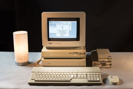 An SM124 on a Mega ST and Megafile 30
.png)
.png)

Related pages
[edit | edit source]- Atari SM124 General Maintenance
- Atari SM124 Troubleshooting Guide
- Atari SM124 Capacitor Replacement Guide
- Atari SM124 Documentation
- Atari SM125, Atari SM146, Atari SM147, Atari SM194
- Atari SC1224
- CRT Discharge Procedure
References
[edit | edit source]- ↑ 1.00 1.01 1.02 1.03 1.04 1.05 1.06 1.07 1.08 1.09 1.10 1.11 "Atari SM124 High-Resolution Monochrome Monitor" and "Atari SM125 High-Resolution Monochrome Monitor", in "Atari ST-Peripheriegeräte", atari-computermuseum.de, https://www.atari-computermuseum.de/st_peri.htm#sm124. Secondary source for the maker, the first showing and sales dates, the end of production, prices, the 1989 facelift, compatibility, dimensions and weight, the original GoldStar models MT-9 and MT-21, and the later monochrome models.
- ↑ 2.0 2.1 2.2 2.3 2.4 Atari Corp., SM124 High-Resolution Monochrome Monitor Owner's Manual, 1985, p. 6, "SM124 Monitor Specifications". File:Atari SM124 Owner's Manual (1985).pdf.
- ↑ 3.0 3.1 3.2 3.3 SM124 Service Manual (MT-9), Specifications, p. 3.
- ↑ 4.0 4.1 SM124 Service Manual (MT-21), Specifications, p. 3.
- ↑ 5.0 5.1 5.2 Atari Corp., Atari Monitor Summary Specifications, memo of 14 May 1986, p. 2, SM 124 column. File:Atari Monitor Summary Specifications (1986-05-14).pdf.
- ↑ 6.0 6.1 6.2 6.3 SM124 Service Manual (MT-9), Theory of Operation, pp. 5-6: video amplifier, vertical and horizontal deflection, power supply.
- ↑ 7.0 7.1 7.2 SM124 Service Manual (MT-21), Theory of Operation, pp. 5-8: video amplifier, vertical and horizontal deflection, TDA4601 power supply.
- ↑ 8.0 8.1 "Atari ST", Wikipedia, section "Monitor". https://en.wikipedia.org/wiki/Atari_ST
- ↑ SM124 Service Manual (MT-9), Safety Precautions, p. 2: maximum operating high voltage 12 kV +1 −2 kV at zero beam current and 220 V AC.
- ↑ Atari, SM124 High-Resolution Monochrome Monitor Service Manual, chassis MT-9, P/N 483-303A, cover. File:Atari SM124 Service Manual (MT-9 chassis).pdf.
- ↑ Atari, SM124 High-Resolution Monochrome Monitor Service Manual, chassis MT-21, P/N 483-351A, cover. File:Atari SM124 Service Manual (MT-21 chassis).pdf.
- ↑ SM124 Owner's Manual, pp. 2-3, "Controlling and Adjusting the Monitor".
- ↑ SM124 Owner's Manual, pp. 1-2, "Connecting the Monitor".
- ↑ Atari Monitor Summary Specifications, 14 May 1986, p. 5, "Signal DIN-connector pin assignment". File:Atari Monitor Summary Specifications (1986-05-14).pdf.
- ↑ 15.0 15.1 15.2 15.3 SM124 Service Manual (MT-9), Replacement Parts List, pp. 26-28.
- ↑ SM124 Service Manual (MT-9), Adjustment and Maintenance, Circuit Protection, p. 3.
- ↑ SM124 Service Manual (MT-9), Voltage Chart, p. 11.
- ↑ 18.0 18.1 SM124 Service Manual (MT-21), Adjustment and Maintenance, p. 3: fuse F901 1.6 A; B+ adjustment VR901 set to 27 V DC.
- ↑ 19.0 19.1 SM124 Service Manual (MT-21), Replacement Parts List, p. 21.
- ↑ SM124 Service Manual (MT-21), Replacement Parts List, p. 22: F901 fuse, time lag 1.6 A 250 V.
- ↑ 21.0 21.1 Pawel Pieczul, "Atari SM124 Monitor", oldcrap.org, 20 October 2019, https://oldcrap.org/2019/10/20/atari-sm124-monitor/. Community source: board photographs of revisions 1.0, 1.2 and 1.3, the note on C716, and a capacitor list taken from the parts removed from the boards.
- ↑ Atari SC1224 Documentation, section on the CA-3 service manual: PDF pages 2 to 5 of that scan belong to a monochrome monitor with schematic P/N 484-476A.