

Atari SC1224
| Atari SC1224 | |
|---|---|
 |
|
| A JVC-built SC1224 (left) and a Goldstar-built SC1224 (right) | |
| Manufacturer | Atari Corporation; built by JVC, Goldstar and Samsung[1] |
| Type | 12-inch RGB colour monitor |
| Release date | July 1985 (JVC, North America); April 1986 (Goldstar)[1] |
| Discontinued | About 1992 (Goldstar)[1] |
| Price | DM 1,198 (Goldstar, 1986); US$399.95 (Samsung, November 1989)[1] |
| Interface | 13-pin DIN, analogue RGB with TTL sync |
| Compatible | Atari 520ST, Atari 1040ST and the other ST models except the ST Book; Falcon030 with an adapter[1] |
| Dimensions | 327 × 290 × 367 mm (CA-3 chassis); 326 × 295 × 377 mm (Version 2), W × H × D[2][3] |
| Weight | 10.7 kg (CA-3 chassis); 10 kg (Version 2)[2][3] |
| Power | 120 V AC 50/60 Hz, 1.0 A (Version 2); 220 V AC 50 Hz, 0.4 A (CA-3 chassis)[3][2] |
| Resolution | 640 × 200 and 320 × 200 (ST medium and low resolution)[4] |
The Atari SC1224 is the 12-inch RGB colour monitor that Atari Corporation sold with the Atari ST range. It shows the ST's low (320 × 200) and medium (640 × 200) resolutions at 15.75 kHz and has a built-in speaker for the ST's sound output.[4][2][5][6] Atari bought the monitor from three manufacturers under the one model number, and the three versions have different cases, boards and service manuals.[1][7] The ST's high resolution (640 × 400) needs the monochrome SM124 and does not display on the SC1224.[4][6]
The monitor contains a colour CRT with an anode supply of 22 to 23 kV and a mains power supply. Read CRT Discharge Procedure before opening the case.[3][8]
Versions
[edit | edit source]| JVC (Version 2) | Goldstar (CA-3 chassis) | Samsung | |
|---|---|---|---|
| Factory code[1] | M1 | N1 | U1 |
| On sale[1] | July 1985 to April 1986, North America | April 1986 to about 1992 | 1987 to autumn 1990, North America |
| Boards | MA-1018A: main, CRT socket, audio and switch boards[9] | Main, CPT (CRT) and power boards[10] | Not documented here |
| Mains | 120 V AC 50/60 Hz, 1.0 A[3] | 220 V AC 50 Hz, 0.4 A[2] | |
| Picture tube | M29JAM60X, 0.385 mm dot trio[3] | M29JLB61X11[11] | 0.38 mm slot mask[1] |
| Anode voltage | 22.0 kV[3] | 23.0 kV nominal, 24.0 kV maximum[8] | |
| Service manual | SC1224 Version 2 Field Service Manual, C070433, February 1986 | SC1224 RGB Color Monitor Service Manual, chassis CA-3 | None found |
atari-computermuseum.de records that a first SC1224 design, based on the monitor planned for the Coleco Adam, never went on sale, and that Atari ordered the JVC set as a stopgap; Atari's own manual calls it "Version 2". It gives the Samsung set the internal name SC1225 and the FCC ID A3L9ONSC1225.[1] The Goldstar set uses a lengthened version of the SM124 case.[1] The JVC and Goldstar cases are easy to tell apart side by side (see the photograph above).[12]
Neither service manual names the maker. The CA-3 manual's dimensions and weight (327 × 290 × 367 mm, 10.7 kg) are those atari-computermuseum.de gives for the Goldstar set; the Version 2 manual's (326 × 295 × 377 mm, 10 kg) are those it gives for the JVC set, and that manual was printed in Japan.[2][3][13][1] Owners of Goldstar sets work from the CA-3 designators, for example R616 for vertical size and R626 for vertical centring.[14]
Specifications
[edit | edit source]| Item | Version 2 (JVC)[3] | CA-3 chassis (Goldstar)[2] |
|---|---|---|
| Picture tube | 12 in, 90° deflection, in-line guns, 0.385 mm dot trio, short persistence | 12 in, 90° deflection, in-line gun, neck 29.1 mm |
| Input | Separate R, G, B analogue, 1.0 V p-p, 75 Ω; H and V sync negative, TTL level | R, G, B analogue; H and V sync TTL level |
| Connector | 13-pin DIN | 13-pin |
| Video bandwidth | 16 MHz (−3 dB) | 18 MHz typical (general information page) |
| Scan rates | 15.75 kHz horizontal, 60 Hz vertical | 15.75 kHz horizontal, 60 Hz vertical |
| Retrace | 16 µs horizontal, 1000 µs vertical | |
| Display area | 216 × 160 mm recommended | 210 mm wide set by the width adjustment, 150 mm high set by the size adjustment[15] |
| Text | 25 rows × 80 columns | |
| Mains | 120 V AC 50/60 Hz, 1.0 A | 220 V AC 50 Hz, 0.4 A |
| Anode voltage | 22.0 kV | 23.0 kV nominal |
Atari's May 1986 summary specification for the ST monitors lists the SC1224 with a 0.38 mm dot pitch, a 13-pin male DIN plug, RGB analogue input at 75 Ω and 0 to 1.0 V p-p, a 16 MHz dot rate, TTL sync with 3.3 kΩ inputs, a 210 × 150 mm display area and 640 × 200 resolution.[4] The CA-3 schematic labels the AC input "100-264V 47-63Hz", while the same manual's specification page gives 220 V 50 Hz.[16][2]
Controls
[edit | edit source]The three versions place the controls differently.[1]
| Version | Front or side | Rear |
|---|---|---|
| Version 2 (JVC) | Power switch with indicator, volume, contrast[17] | Brightness, vertical hold, vertical height, vertical position, horizontal position, horizontal hold, all screwdriver-adjusted[17] |
| CA-3 (Goldstar) | On/volume knob (turns the monitor on), contrast, brightness[5] | V-LIN (R635), V-SIZE (R616), V-HOLD (R603), H-POSITION (R710), H-HOLD (R716)[5] |
| Samsung | Contrast, brightness, volume | Vertical hold, vertical size, horizontal phase[1] |
Goldstar's manual tells the owner to switch the monitor on before the computer. The degaussing coil runs for about one second at switch-on and needs the monitor to stay off for at least ten minutes before it works fully again.[5][15]
Hardware
[edit | edit source]Version 2 (JVC)
[edit | edit source]The MA-1018A set has four parts: the main board, the CRT socket board, the audio board and the power switch board.[9] The 120 V mains is rectified directly by D1901 to D1904 and smoothed by C1904 (470 µF 200 V). The regulator IC1901, an STR30125-A (printed STR3125-A on the power circuit page), produces the 125 V B1 line. A mains transformer, T1901, feeds the bridge D1905 and C1905 (1000 µF 25 V), which supply Q1501, the starter for the horizontal oscillator.[18] The horizontal output transistor is Q1522, a 2SD1426 or 2SD1554, driven by Q1521 (2SD866A) through T1521. An HA11235 (IC1501) is the horizontal and vertical oscillator and AFC, an AN5515 (IC1421) the vertical output, an AN5355 (IC1001) the RGB amplifier and switch, an AN5265 (IC1601) the audio amplifier and a TC4528BP (IC1801) the sync pulse former.[19][9]
CA-3 chassis (Goldstar)
[edit | edit source]The CA-3 has a separate switch-mode power board. An STR41090 (IC950) drives the transformer T950, and the secondaries give 115 V, 12 V and 14 V through D960 to D962, filtered by C961, C963 and C965. Q950 and R951 protect the switching transistor against current surges.[20] The mains fuse F901 is 3.15 A.[11] On the main board an LA7850 (IC701) handles sync, the horizontal oscillator and AFC, IC601 (an LA7830 on the schematic; the parts list numbers it IC801) is the vertical output, and Q702 drives the horizontal output transistor Q703 (2SD1453) through T701. An X-ray protection circuit on IC701 pin 13 stops the horizontal oscillator if the flyback pulse rises too far; it latches, and the monitor must be switched off for at least 30 seconds to reset it.[20][10][16] The sound IC is an AN5265 (IC401), the same type as in the JVC set.[11]
Connecting to a computer
[edit | edit source]The SC1224 plugs into the ST's 13-pin monitor socket. The attached monitor decides which resolutions the ST offers, so software written for the colour modes needs a colour monitor such as the SC1224.[6] atari-computermuseum.de lists the SC1224 as usable on every ST model except the ST Book, and on the Falcon030 with an adapter.[1] On the Version 2 the signal cable is a separate DIN-to-DIN lead; on the Goldstar and Samsung sets it is fixed to the monitor.[1]
| Pin | Signal | Pin | Signal |
|---|---|---|---|
| 1 | Audio | 8 | 12 V pull-up |
| 2 | Not connected | 9 | Horizontal sync |
| 3 | Not connected | 10 | Blue |
| 4 | Mono/RGB (ground for mono, not connected for RGB) | 11 | Video (monochrome) |
| 5 | Not connected | 12 | Vertical sync |
| 6 | Green | 13 | Ground |
| 7 | Red |
Known faults
[edit | edit source]Owners report dried or leaking electrolytic capacitors, failed flyback transformers and failed horizontal output transistors. One owner found three leaking capacitors on the power board, one of them the large reservoir, after the monitor lost picture and sound and smoked.[22] An owner who recapped an SC1435 and advised another on an SC1224 named the flyback and the horizontal deflection transistor as the other parts that tend to fail.[14] See Atari SC1224 Troubleshooting Guide and Atari SC1224 Capacitor Replacement Guide.
Documentation
[edit | edit source]- Atari SC1224 Documentation: the CA-3 (Goldstar) service manual, the CA-3 schematic and troubleshooting charts, the Version 2 (JVC) field service manual C070433, and Atari's May 1986 monitor summary specifications. No service manual for the Samsung set has been found.
Gallery
[edit | edit source]-
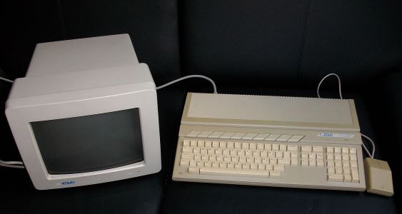 An SC1224 with an Atari 1040STE (Stefan Didam, CC BY-SA 3.0)
 -
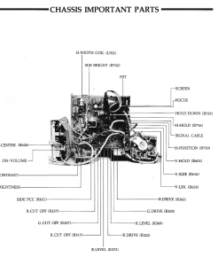 Adjustment points on the CA-3 chassis (Atari service manual)
 -
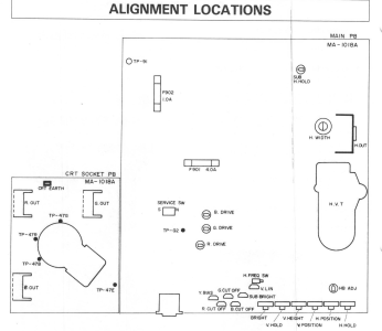 Alignment locations on the Version 2 boards (Atari service manual)


Related pages
[edit | edit source]- Atari SC1224 General Maintenance
- Atari SC1224 Troubleshooting Guide
- Atari SC1224 Capacitor Replacement Guide
- Atari SC1224 Documentation
- Atari SC1425, Atari SC1435, Atari PTC1426
- CRT Discharge Procedure
References
[edit | edit source]- ↑ 1.00 1.01 1.02 1.03 1.04 1.05 1.06 1.07 1.08 1.09 1.10 1.11 1.12 1.13 1.14 1.15 "Atari SC1224 RGB Color Monitor", in "Atari ST-Peripheriegeräte", atari-computermuseum.de, https://www.atari-computermuseum.de/st_peri.htm#sc1224. Secondary source for the three manufacturers and factory codes, first showing, sales periods, prices, controls, connection, compatibility, slot-mask pitches, the SC1225 name and FCC ID, and the Coleco Adam origin.
- ↑ 2.0 2.1 2.2 2.3 2.4 2.5 2.6 2.7 SC1224 Service Manual (CA-3), General Information and Specifications (PDF p. 6).
- ↑ 3.0 3.1 3.2 3.3 3.4 3.5 3.6 3.7 3.8 Atari Corporation, SC1224 Version 2 Field Service Manual, C070433, February 1986, Specifications, p. 2. File:Atari SC1224 Version 2 Field Service Manual C070433.pdf.
- ↑ 4.0 4.1 4.2 4.3 Atari Corp., Atari Monitor Summary Specifications, memo from Tom Brightman, 14 May 1986, SC1224 column. File:Atari Monitor Summary Specifications (1986-05-14).pdf.
- ↑ 5.0 5.1 5.2 5.3 SC1224 Service Manual (CA-3), Control Operation, printed p. 5 (PDF p. 7).
- ↑ 6.0 6.1 6.2 "Atari ST", Wikipedia, section "Monitor". https://en.wikipedia.org/wiki/Atari_ST
- ↑ "CRT Displays", AtariForumWiki (mirror at temlib.org), https://temlib.org/AtariForumWiki/index.php/CRT_Displays. Secondary source; lists Goldstar, JVC and Samsung SC1224 versions.
- ↑ 8.0 8.1 Atari, SC1224 RGB Color Monitor Service Manual, chassis CA-3, Safety Precautions (PDF p. 6). File:Atari SC1224 Service Manual (CA-3 chassis).pdf.
- ↑ 9.0 9.1 9.2 SC1224 Version 2 Field Service Manual, Schematic Diagram (PDF p. 32).
- ↑ 10.0 10.1 SC1224 Service Manual (CA-3), Replacement Parts List, main board, printed pp. 30-31 (PDF p. 21).
- ↑ 11.0 11.1 11.2 SC1224 Service Manual (CA-3), Replacement Parts List, main, CPT and power boards, printed pp. 31-32 (PDF pp. 21-22).
- ↑ Blake Patterson, photograph of a JVC and a Goldstar SC1224, 2007, CC BY 2.0. File:Atari SC1224 JVC and Goldstar versions.jpg.
- ↑ SC1224 Version 2 Field Service Manual, PDF p. 33, imprint "Printed in Japan".
- ↑ 14.0 14.1 "Atari SC1224", exxos's Atari, Amiga & retro forum, thread of May 2020, post by derkom of 21 May 2020. https://www.exxosforum.co.uk/forum/viewtopic.php?t=2803. Community report.
- ↑ 15.0 15.1 SC1224 Service Manual (CA-3), Adjustment and Maintenance, printed p. 6 (PDF p. 8).
- ↑ 16.0 16.1 Atari, CA-3 Chassis Schematic Diagram, P/N 484-257A, power board and vertical output. File:Atari SC1224 CA-3 Chassis Schematic and Troubleshooting Charts.pdf, PDF p. 1.
- ↑ 17.0 17.1 SC1224 Version 2 Field Service Manual, Functions, p. 4.
- ↑ SC1224 Version 2 Field Service Manual, Power Circuit, p. 29.
- ↑ SC1224 Version 2 Field Service Manual, Replacement Parts List, pp. 12-13.
- ↑ 20.0 20.1 SC1224 Service Manual (CA-3), Theory of Operation, printed p. 5 (PDF p. 7).
- ↑ Atari Corp., Atari Monitor Summary Specifications, 14 May 1986, p. 5, "Signal DIN-connector pin assignment". File:Atari Monitor Summary Specifications (1986-05-14).pdf.
- ↑ "Dead SC1224", Atari-Forum, thread started 25 March 2010, posts by MaLICiouS of 26 March 2010. https://www.atari-forum.com/viewtopic.php?t=18975. Community report.