

File:Atari SC1224 Version 2 alignment locations.png

Summary
[edit | edit source]

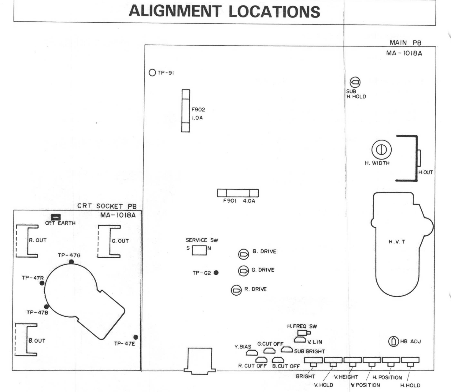
"Alignment locations" from Atari's SC1224 Version 2 Field Service Manual (C070433, February 1986), page 6: a layout of the MA-1018A main board and CRT socket board of the JVC-built SC1224 Version 2 showing the fuses F901 (4.0 A) and F902 (1.0 A), the drive, cut-off, bias and brightness presets, the HB ADJ preset, the H.FREQ and service switches, the width coil, the rear-panel controls and the test points TP-G2 and TP-47R, G, B and E. Rendered at 200 dpi and cropped.
Source
[edit | edit source]

Rendered from File:Atari SC1224 Version 2 Field Service Manual C070433.pdf, PDF page 6.
Author
[edit | edit source]

Atari Corporation
Licence
[edit | edit source]

Copyright Atari Corporation. Hosted for preservation and repair reference, with the source cited.
File history
Click on a date/time to view the file as it appeared at that time.
| Date/Time | Thumbnail | Dimensions | User | Comment | |
|---|---|---|---|---|---|
| current | 14:46, 4 October 2026 | | 1,475 × 1,281 (231 KB) | Josh (talk | contribs) | Upload for Atari SC1224 pages; source and licence on file page |
You cannot overwrite this file.
File usage
The following 2 pages use this file:
