

File:Atari SM124 MT-9 main board layout (service manual).png

Summary
[edit | edit source].png&veaction=edit§ion=1)
.png&action=edit§ion=1)
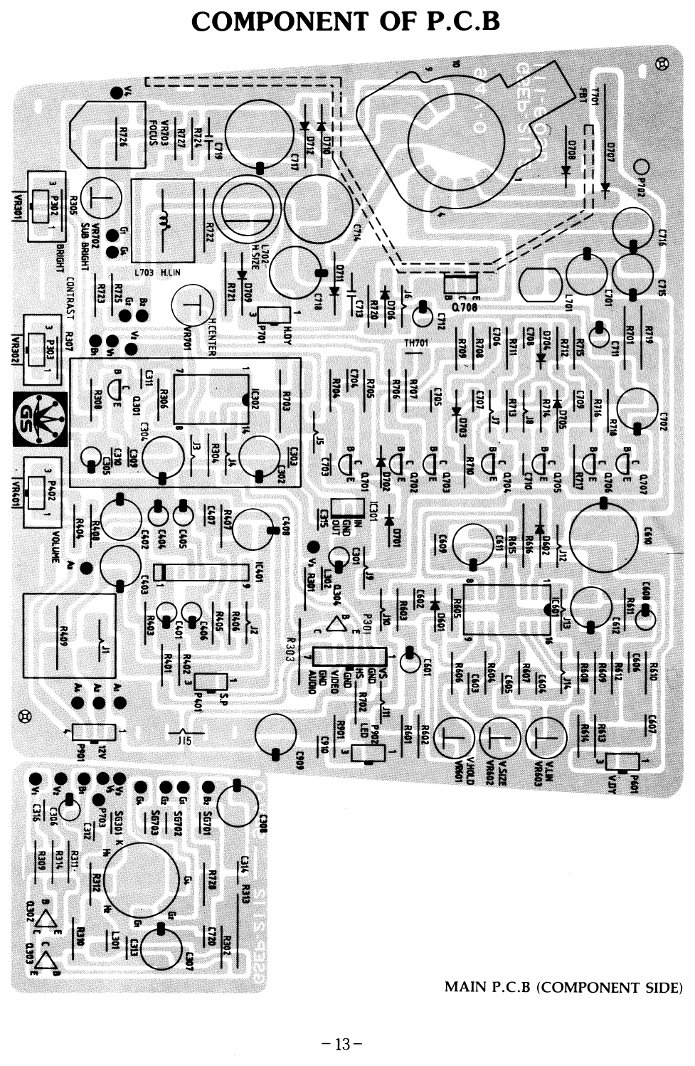
Component-side layout of the main board of the Atari SM124 on chassis MT-9, with the CRT board at bottom left, showing the designators of the presets (VR601 V-HOLD, VR602 V-SIZE, VR603 V-LIN, VR701 H-CENTER, VR702 SUB BRIGHT, VR703 FOCUS, L702 H-SIZE, L703 H-LIN) and of the electrolytic capacitors. Rendered at 150 dpi from page 13 of File:Atari SM124 Service Manual (MT-9 chassis).pdf.
Source
[edit | edit source].png&veaction=edit§ion=2)
.png&action=edit§ion=2)
Atari, SM124 Service Manual, chassis MT-9, P/N 483-303A, p. 13, "Component of P.C.B". Scan from Internet Archive item sm-124-service-manual-mt-9.
Author
[edit | edit source].png&veaction=edit§ion=3)
.png&action=edit§ion=3)
Atari Corp.
Licence
[edit | edit source].png&veaction=edit§ion=4)
.png&action=edit§ion=4)
Copyright Atari Corp. Used here for repair reference, with the source cited.
File history
Click on a date/time to view the file as it appeared at that time.
| Date/Time | Thumbnail | Dimensions | User | Comment | |
|---|---|---|---|---|---|
| current | 11:25, 6 October 2026 | | 977 × 1,498 (475 KB) | Josh (talk | contribs) | Upload Atari SM124 MT-9 main board layout (service manual) for the SM124 pages |
You cannot overwrite this file.
File usage
The following 2 pages use this file:
.png&oldid=24825)