

File:DECmate I VT278 rear panel diagram.png
Size of this preview: 800 × 524 pixels. Other resolution: 1,390 × 910 pixels.

Original file (1,390 × 910 pixels, file size: 39 KB, MIME type: image/png)
Summary
[edit | edit source]

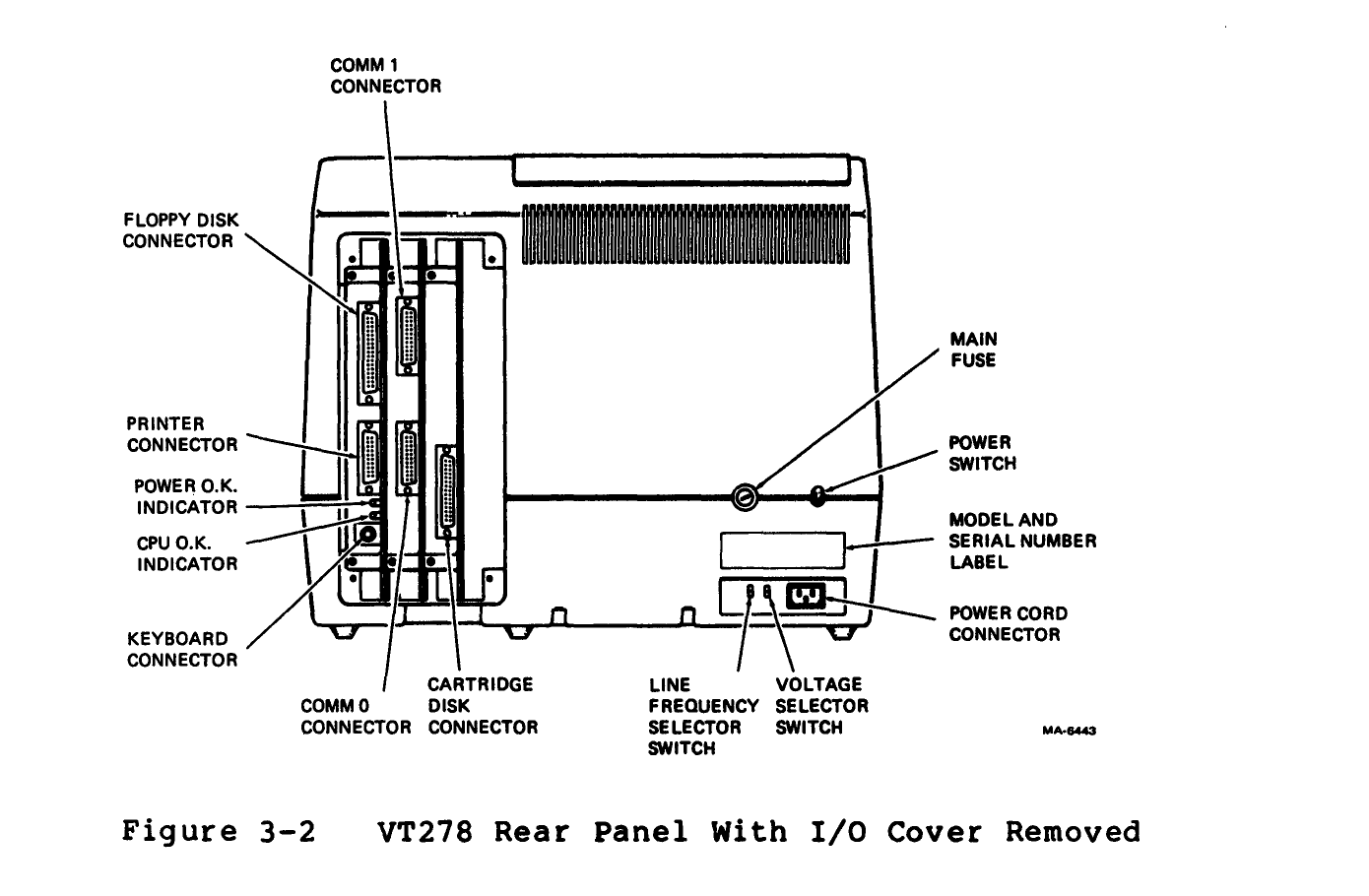
DEC's Figure 3-2, VT278 Rear Panel With I/O Cover Removed, showing the floppy disk, printer, keyboard, COMM 0, COMM 1 and cartridge disk connectors, the POWER O.K. and CPU O.K. indicators, the main fuse, power switch, line frequency and voltage selector switches and the power cord connector.
Source
[edit | edit source]

Rendered from page 3-3 of the DECmate System Architecture Manual, EK-VT278-HR-001 (File:DECmate System Architecture Manual (EK-VT278-HR-001).pdf)
Author
[edit | edit source]

Digital Equipment Corporation.
Licence
[edit | edit source]

Copyright Digital Equipment Corporation. Reproduced from the manual for repair reference, with the source cited.
File history
Click on a date/time to view the file as it appeared at that time.
| Date/Time | Thumbnail | Dimensions | User | Comment | |
|---|---|---|---|---|---|
| current | 21:23, 1 October 2026 | | 1,390 × 910 (39 KB) | Josh (talk | contribs) | Upload DECmate diagram rendered from DEC documentation |
You cannot overwrite this file.
File usage
The following 2 pages use this file:
