

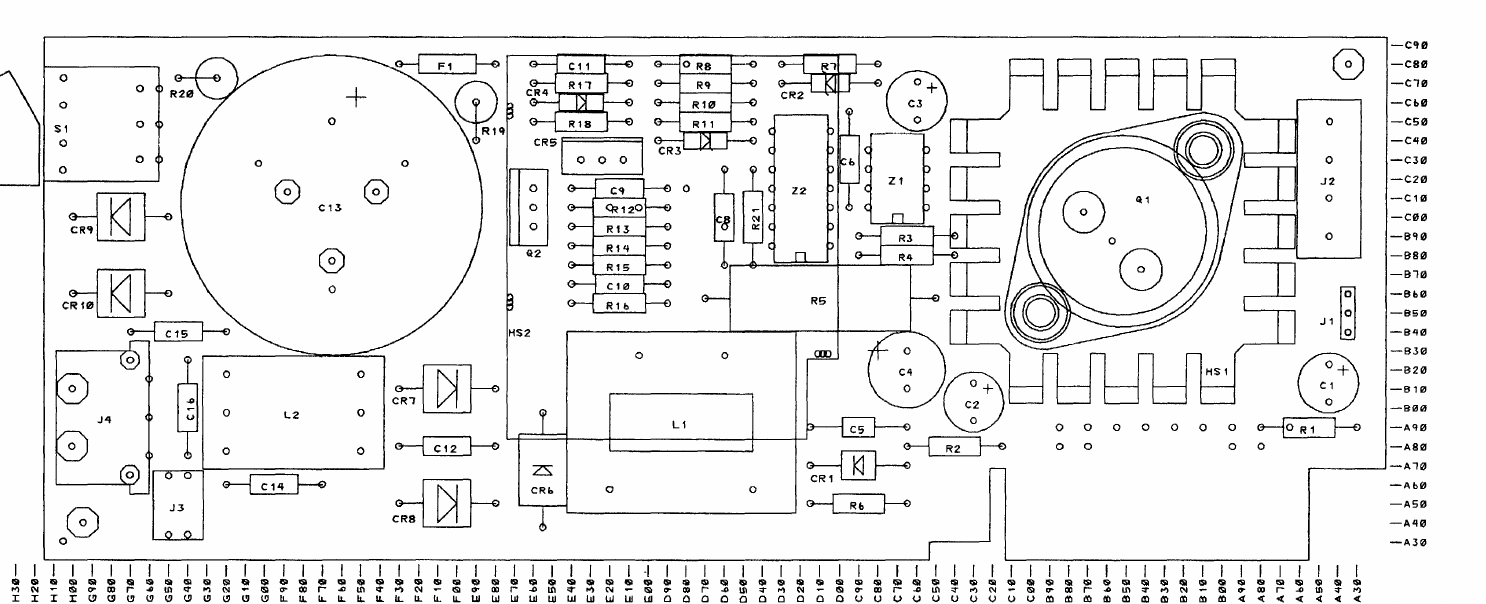
File:IBM PCjr Power Board component placement (Technical Reference B-24).png

Summary
[edit | edit source].png&veaction=edit§ion=1)
.png&action=edit§ion=1)
Component placement drawing of the IBM PCjr Power Supply Board (the internal second stage of the PCjr power supply), from IBM's IBM PCjr Technical Reference, November 1983, Appendix B, p. B-24 ("Power Supply Board (Sheet 2 of 2)"). It shows the positions of C1 to C4, C13 (the large reservoir capacitor), the rectifiers CR7 to CR10, fuse F1, switch S1, regulator Q1 on heatsink HS1 and the connectors J1 to J4. Cropped from a 220 dpi render of the page; the matching schematic is on p. B-23.
Source
[edit | edit source].png&veaction=edit§ion=2)
.png&action=edit§ion=2)
http://bitsavers.org/pdf/ibm/pc/pc_jr/PCjr_Technical_Reference_Nov83.pdf, PDF page 522 (retrieved 2026-09-30). The appendix is also hosted as File:IBM PCjr Technical Reference Appendix B Logic Diagrams (November 1983).pdf.
Author
[edit | edit source].png&veaction=edit§ion=3)
.png&action=edit§ion=3)
International Business Machines Corporation
Licence
[edit | edit source].png&veaction=edit§ion=4)
.png&action=edit§ion=4)
Copyright International Business Machines Corporation 1983. Not freely licensed. Used for repair reference.
File history
Click on a date/time to view the file as it appeared at that time.
| Date/Time | Thumbnail | Dimensions | User | Comment | |
|---|---|---|---|---|---|
| current | 20:46, 30 September 2026 | | 1,486 × 604 (81 KB) | Josh (talk | contribs) | PCjr Power Board placement drawing, TR p. B-24 |
You cannot overwrite this file.
File usage
The following page uses this file:
.png&oldid=16480)