

IBM PCjr Capacitor Replacement Guide

The IBM PCjr's electrolytic and tantalum capacitors are on the system board, the Power Board inside the system unit, the infrared receiver board, the 64KB Memory and Display Expansion and the diskette-drive adapter. IBM's service manual works at field-replaceable-unit (FRU) level and lists no component values,[1] but the logic diagrams in Appendix B of IBM's Technical Reference print them.[2]
How the PCjr is powered
[edit | edit source]IBM's supply is a 33 W, two-stage design. The first stage is an external transformer with a single-fuse-protected, extra-low-voltage AC output. The second stage is the Power Board, a card mounted vertically in the system board, which converts that AC into +5 V, +12 V and −6 V.[3] IBM's connector specification gives the transformer output as "Pin 1 – 17 Vac, Pin 2 – GND, Pin 3 – 17 Vac".[3] The ageing electrolytics of the supply are therefore on the Power Board, not in the external transformer.
IBM's schematic of the Power Board shows the transformer input on J4, a bridge of four 3 A rectifiers (CR7 to CR10) charging C13, switch S1 and a 5 A fuse F1, a +12 V regulator (Q1, on heatsink HS1), and a switching +5 V stage built round controller Z2, Darlington Q2 and inductor L1, with C4 on its output.[2] Brutman reports a short 33 W and a long 45 W Power Board. IBM's drawings come from the November 1983 Technical Reference and do not say which board they show.[4]
| Rail | Minimum load | Maximum load | Regulation | Range |
|---|---|---|---|---|
| +5 V | 1.5 A | 3.6 A | ±5 % | 4.75 to 5.25 V |
| +12 V | 0.04 A | 1.2 A | ±5 % | 11.40 to 12.60 V |
| −6 V | 0.0 A | 0.025 A | ±16 % | −5.04 to −6.96 V |
The −6 V output is present only when +5 V carries at least 1.5 A, so a lightly loaded Power Board on the bench may show no −6 V without being faulty.[3] The +5 V over-current protection trips at 3.9 ± 0.25 A and resets once the fault is removed and the power has been off for at least 5 seconds. The +12 V protection trips at 2.2 ± 0.9 A; IBM's table does not mark it as resettable. Over-voltage protection on both rails is by fuse F1.[3] A shorted capacitor on the +5 V or +12 V rail therefore holds the machine off until the short is removed.
Power Board capacitor list
[edit | edit source].png)
| Ref | Value | Voltage | Drawn as | Console5 list |
|---|---|---|---|---|
| C1 | 22 µF | 25 V | Polarised | 1000 µF 16 V |
| C2 | 100 µF | 16 V | Polarised | 100 µF 16 V |
| C3 | 22 µF | 25 V | Polarised | 22 µF 25 V |
| C4 | 1000 µF | 12 V | Polarised | 1000 µF 12 V, low ESR |
| C13 | 15,000 µF (printed "15,00 UF") | 25 V | Large can | 15000 µF 25 V |
| C5 | 1000 pF | Not printed | Non-polarised | Not listed |
| C6 | 1000 pF | 50 V | Non-polarised | Not listed |
| C8 | 47 pF | 50 V | Non-polarised | Not listed |
| C9 | 220 pF | 25 V | Non-polarised | Not listed |
| C10 | 0.1 µF | 25 V | Non-polarised | Not listed |
| C11 | 0.1 µF | 25 V | Non-polarised | Not listed |
| C12 | 0.10 µF | 100 V | Non-polarised | Not listed |
| C14 | 0.047 µF | 100 V | Non-polarised | Not listed |
| C15 | 0.047 µF | 100 V | Non-polarised | Not listed |
| C16 | 0.1 µF | 100 V | Non-polarised | Not listed |
There is no C7 on the drawing.[2] The Console5 column is a community list read from boards, given for comparison.[5] It agrees with IBM on C2, C3, C4 and C13 but gives C1 as 1000 µF 16 V where IBM's schematic prints 22 µF 25 V. Read the markings on the part fitted to your board before ordering. IBM prints 12 V for C4; a replacement rated 16 V or more meets that.
C13 is the reservoir on the rectified transformer output. Console5 notes that the original has three legs with very wide spacing, that modern replacements are smaller two-legged parts, and that the board already has solder points for the newer spacing, needing only a slight change of orientation. Its cap map marks one hole as the only positive point, with the others usable for negative.[5]
Other boards
[edit | edit source]| Board | Ref | Value | Source |
|---|---|---|---|
| System board | C2, C4, C8, C12, C13, C22, C23, C35, C38, C39, C45 | 10 µF, polarised (IBM prints no voltage; Console5 gives 16 V) | IBM sheets 1, 6, 10 and 13 (pp. B-3, B-8, B-12, B-15);[2] Console5[5] |
| Infrared receiver board | C1, C4, C6 | 10 µF, polarised (IBM prints no voltage; Console5 gives 50 V) | IBM p. B-42;[2] Console5[5] |
| 64KB Memory and Display Expansion | C1 | 10 µF on +5 V (IBM); 16 V (Console5) | IBM sheet 3, p. B-27;[2] Console5[5] |
| Diskette-drive adapter | C1; C5 | 1 µF 50 V; 10 µF 16 V | Console5[5] |
On IBM's sheets C2, C4, C22, C38 and C45 are on +5 V, C39 on +12 V and C8 on −6 V (sheet 13, p. B-15); C12 and C13 are on the input and output of the LM340T regulator VR1 (sheet 6, p. B-8), C23 is on the reset input of the 8284A clock generator (sheet 1, p. B-3) and C35 is in the audio circuit (sheet 10, p. B-12). Console5's list has the same positions except that it gives C59 as a 10 µF 16 V part and leaves out C23. IBM's sheet 10 prints C59 as 680 pF, on the IR test data line, so the table follows IBM.[2][5] The diskette-drive adapter values are Console5's alone. On IBM 51xx boards the 10 µF 16 V filter capacitors are tantalums, usually marked "106 16V" or "10µF 16V".[6] minuszerodegrees.net's tantalum pages name the 5150, 5155 and 5160, not the PCjr.
Failure modes
[edit | edit source]Tantalum capacitors fail either open or short. A short overloads the supply so that it will not run. Failures most often happen on power-up or within about thirty seconds of it, and are more likely on a board left unpowered for years than on one used every few months. Some fail with sparks or burst open; many show no visible damage at all.[6]

On the PCjr a short on +5 V or +12 V trips the Power Board's over-current protection and the machine stays dead.[3] The Power Board electrolytics age by drying out, which raises ripple and lets the rails sag under load.
Finding a short
[edit | edit source]IBM's power fault procedure isolates the failing FRU by removal:[1]
- Disconnect everything outside the system unit except the transformer (IBM leaves its service plug fitted). If the machine now gives one beep, reconnect the devices one at a time until the fault returns.
- Remove the 64KB Memory and Display Expansion and try again.
- Disconnect the diskette-drive adapter, the diskette-drive power cable, the drive fan cable and the internal modem, and try again.
- Unplug the transformer from the system unit and measure its output plug: pin 1 to pin 3 must read 15.0 to 30.0 V AC.
- With the transformer connected and the drive cables unplugged, measure the Power Board's diskette-drive connector: pin 1 to pin 2, +11.4 to +12.6 V; pin 4 to pin 3, +4.7 to +5.3 V.
- If the voltages are wrong, IBM replaces the Power Board. If they are right, IBM tries a new Power Board and, if there is still no beep, replaces the system board.
To go below FRU level, switch off, then measure resistance from each rail to ground on the suspect board. A reading near zero points to a shorted part on that rail; lift the capacitors on the rail one at a time to find it.
A machine that fails only with several sidecars fitted may be over its power budget rather than faulty. IBM gives 400 mA of +5 V as the spare capacity of a fully configured machine, and Brutman reports erratic operation from heavy sidecar loads.[3][4]
Replacement
[edit | edit source]- Unplug the transformer from the wall and from the system unit before working on the Power Board.
- Before removing C13, discharge it through a resistor and check with a meter. It is a low-voltage part, but at 15,000 µF it can deliver a large current into a short.
- Note the polarity of each part before removing it.
- Fit parts of the same capacitance and at least the voltage rating on IBM's drawing, and observe the polarity marked on the board.
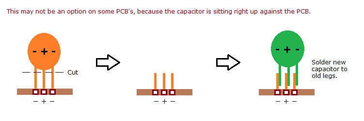
- Where the old part's legs allow, minuszerodegrees.net's "solder new capacitor to old legs" method avoids reheating the pads: cut the old legs a few millimetres above the board and solder the new part to the stubs. The method cannot be used where the part sits flat on the board.[7]

After recapping
[edit | edit source]- Advanced POST should end with one beep.[1]
- Check the Power Board's diskette-drive connector against IBM's limits: pin 1 to pin 2, +11.4 to +12.6 V; pin 4 to pin 3, +4.7 to +5.3 V. The drive fan connector should read +11.4 to +12.6 V from pin 2 to pin 1 and from pin 2 to pin 3.[1][8]
- Remember that −6 V needs at least 1.5 A on +5 V before it appears.[3]
References
[edit | edit source]- ↑ 1.0 1.1 1.2 1.3 IBM, Personal Computer PCjr Hardware Maintenance and Service, first edition, September 1983, hosted as File:IBM PCjr Hardware Maintenance and Service (September 1983).pdf. Power PIC, pp. 3-020-1 to 3-020-11; parts catalogue, pp. 6-7 to 6-13.
- ↑ 2.0 2.1 2.2 2.3 2.4 2.5 2.6 IBM, IBM PCjr Technical Reference, November 1983, Appendix B, "Logic Diagrams", hosted as File:IBM PCjr Technical Reference Appendix B Logic Diagrams (November 1983).pdf. Power Supply Board schematic p. B-23 and placement p. B-24; system board sheets 1, 6, 10 and 13 (pp. B-3, B-8, B-12, B-15); 64KB Memory and Display Expansion sheet 3, p. B-27; Infra-Red Receiver Board p. B-42.
- ↑ 3.0 3.1 3.2 3.3 3.4 3.5 3.6 IBM, IBM PCjr Technical Reference, November 1983, "System Power Supply", pp. 2-135 to 2-138 (outputs p. 2-136, protection p. 2-137, connector specifications p. 2-138), hosted as File:IBM PCjr Technical Reference.pdf.
- ↑ 4.0 4.1 Mike Brutman, "PCjr Hardware Notes", "The Power Supply". Community reference. Short (33 W) and long (45 W) Power Boards; 400 mA of +5 V spare on a fully configured machine; power sidecars; no system fan.
- ↑ 5.0 5.1 5.2 5.3 5.4 5.5 5.6 Console5 Tech Wiki, "IBM PCjr", revision of 12 January 2017. Secondary source: a community capacitor list, read from boards, for the main board, the 33 W Power Board, the IR receiver board, the 64K memory card and the diskette controller, with cap maps.
- ↑ 6.0 6.1 minuszerodegrees.net, "Commonly Failing Electronic Components (in vintage computers)". Community reference based on the author's repairs of IBM 51xx machines: tantalum failure modes, overloaded supplies, failure on power-up, and the 10 µF 16 V parts used by IBM.
- ↑ minuszerodegrees.net, SNCTOL diagram, "Solder new capacitor to old legs". Drawn for IBM 51xx boards.
- ↑ IBM, Personal Computer Family Service Information Manual, SA38-0037-00, July 1989, chapter 2, "Power Diagnostic Tips", pp. 2-7 to 2-8, hosted as IBM Personal Computer Family Service Information Manual.
Related pages
[edit | edit source]- IBM PCjr
- IBM PCjr Maintenance Guide
- IBM PCjr Troubleshooting Guide
- IBM PC (5150) Capacitor Replacement Guide
- Capacitor Failure Symptoms