

IBM PS/2 Model 50
 | |
 | |
| IBM PS/2 Model 50 (8550) | |
| Specifications | |
|---|---|
| Manufacturer | IBM |
| Type | Desktop personal computer |
| Released | 2 April 1987 (8550-021); 2 June 1988 (Model 50 Z, 8550-031 and -061) |
| Intro price | US$3,595 (021); US$3,995 (031); US$4,595 (061)[1][2] |
| CPU | Intel 80286 at 10 MHz; one wait state (021), zero wait states with 85 ns memory (50 Z) |
| Memory | 1 MB on the system board (2 MB on the 50 Z); 7 MB system maximum (021), 16 MB (50 Z) |
| Storage | 1.44 MB 3.5-inch diskette drive; 20 MB (021), 30 MB (031) or 60 MB (061) fixed disk |
| Display | VGA on the system board, 256 KB video memory |
| Sound | Speaker |
| Dimensions | 360 × 420 × 140 mm (W × D × H)[3] |
| Weight | 9.55 kg[3] |
| OS / Firmware | IBM DOS 3.30; OS/2 Standard and Extended Editions |
| Model no. | 8550 |
The IBM Personal System/2 Model 50 (machine type 8550) is a desktop computer with a 10 MHz Intel 80286 and IBM's Micro Channel bus. IBM announced it on 2 April 1987, with the IBM PS/2 Model 30, IBM PS/2 Model 60 and IBM PS/2 Model 80, as the 8550-021 at US$3,595, and described it as the entry-level Micro Channel system of the new family.[1] The Model 50 Z (8550-031 and 8550-061), announced on 2 June 1988, has faster memory running with no wait states, up to 2 MB on the system board, and 30 MB or 60 MB fixed disks with the controller built into the drive.[2]
Models
[edit | edit source]| Submodel | Announced | System board | Memory as shipped | Fixed disk |
|---|---|---|---|---|
| 8550-021 | 2 April 1987 | Type 1 | 1 MB, two 512 KB modules, one wait state | 20 MB, 80 ms |
| 8550-031 | 2 June 1988 | Type 2 | 1 MB, one 85 ns module, zero wait states | 30 MB, 39 ms |
| 8550-061 | 2 June 1988 | Type 2 | 1 MB, one 85 ns module, zero wait states | 60 MB, 27 ms |
Sources: the announcement letters, IBM's product specification sheets and the October 1990 Technical Reference.[1][2][4][5] The Type 1 board reports model byte FC, submodel 04, revision 00; the Type 2 reports FC, 04, 03. The Type 2 board also accepts a 120 ns 1 MB module, which runs with one wait state, and a 2 MB 85 ns module.[5]
System board
[edit | edit source]The Model 50 planar exists as P/N 90X9161 and 15F6969; the Model 50 Z planar is FRU 90X9533.[6][7] IBM's 1994 parts list gives system board FRU 72X8516 for the 021 and 10G4005 for the 031 and 061.[8]
| Designator | Device |
|---|---|
| ZM36 | Intel 80286, 10 MHz |
| ZM55 | 80287 socket |
| ZM47 | Motorola MC146818A real-time clock and CMOS RAM |
| Y3 | 32.768 kHz crystal for the clock |
| ZM13–ZM16 | BIOS, four 27256 EPROMs |
| ZM12 | 72X7377 DMA controller |
| ZM71 | 72X7385 bus controller |
| ZM74 | 72X8299 I/O controller |
| ZM75 | Intel 8272A diskette controller |
| ZM82 | Intel P8042AH keyboard controller |
| ZM84 | NS16550 UART |
| ZM96, ZM104 | 8259A interrupt controllers |
| ZM109 | 72X8287 VGA controller |
| ZM127 | Inmos IMSG171 RAMDAC |
| ZM21, ZM22 | 30-pin memory sockets |
| F1 | Keyboard and mouse fuse, 3 A 250 V |
| J1 | Battery and speaker connector |
| J5 | Diskette riser slot |
| J9 | Fan connector |
| J10 | Slot for the fixed-disk adapter |
| J11 | Channel slot with the auxiliary video extension |
| J12, J13 | Channel slots |
| J19, J20 | Mouse and keyboard ports |
The system board has 128 KB of ROM, 64 bytes of CMOS RAM with the real-time clock, 256 KB of video memory, eight DMA channels, 16 level-sensitive interrupt levels, the keyboard and auxiliary-device controller with password security, a diskette controller for 720 KB and 1.44 MB media, a serial port and a bidirectional parallel port.[3] The BIOS is split into a compatibility BIOS (CBIOS), addressing up to 1 MB, and an advanced BIOS (ABIOS) for multitasking operating systems, addressing up to 16 MB.[1]
Micro Channel slots
[edit | edit source]There are four 16-bit channel connectors. One carries the auxiliary video extension and one is taken by the fixed-disk adapter, which leaves three for expansion cards.[3][1] IBM's load limit for each connector is 1.6 A at +5 V, 0.175 A at +12 V and 0.040 A at −12 V.[5]
Memory
[edit | edit source]The 021's Type 1 board has two 30-pin sockets holding two 512 KB × 9 modules that run with one wait state; their timing is like a 150 ns Hitachi HB61009BR-15. The 50 Z's Type 2 board has one 72-pin socket and shipped with a 1 MB 85 ns module.[5] Memory beyond the system board goes on Micro Channel adapters. IBM's 1987 announcement gives the 021 a 7 MB physical maximum; the 50 Z announcement gives 16 MB, using the 0–8 MB Expanded Memory Adapter/A, whose memory runs with one wait state.[1][2]
Video
[edit | edit source]The VGA is on the system board, with 256 KB of video memory. It supports 720 × 400 text, 640 × 480 graphics and 256 colours or 64 shades of grey at a time, and is compatible with CGA and EGA modes.[3][1][9] The slot with the auxiliary video extension takes video adapters designed to work with the system-board VGA.[9] The 50 Z uses the 15F6864 VGA controller at ZM51.[7]
Storage
[edit | edit source]Diskette
[edit | edit source]The diskette controller connects through one 40-pin connector on the system board. A bus adapter plugs into it and carries signals and power for up to two 3.5-inch drives.[9] The machine ships with one 1.44 MB drive; IBM's specification is 80 tracks at 135 tracks per inch, two heads, 500,000 bit/s and 300 rpm ±1.5 %.[1] IBM's 1994 FRU numbers are 64F0207 for the drive and 72X8524 for its bus adapter.[8]
PS/2 3.5-inch drives are direct drive and have no belt; the Mitsubishi MF355C turns its spindle directly with a brushless DC motor at 300 rpm.[10] Their usual fault is surface-mount electrolytic capacitors on the drive board that go open or high-ESR and leak.[11]
Fixed disk
[edit | edit source]The fixed disk plugs into an adapter in the dedicated slot J10.[6][3]
| Submodel | Drive (IBM FRU) | Adapter | Access time |
|---|---|---|---|
| 8550-021 | 20 MB, 72X8522 | ST-506 adapter: FRU 72X8505 in IBM's 1994 list; Ardent Tool records 90X8070 (early) and 90X8642 (later) | 80 ms |
| 8550-031 | 30 MB, 6128287, controller in the drive | Passive riser | 39 ms |
| 8550-061 | 60 MB, 6128294, controller in the drive | Passive riser 90X9441 | 27 ms |
Sources: IBM's parts list and announcements, and Ardent Tool.[8][2][4][12]
The 30 MB and 60 MB drives are a disk and a Micro Channel controller built as one unit. IBM's software treats the 60 MB drive as ESDI, but in Peter Wendt's account it is not a true ESDI drive; true ESDI controllers and drives were used in the Model 60 and Model 80 towers. The 021's BIOS lacks the code for these drives, so IBM's 60 MB upgrade for the 021 came with a riser carrying its own BIOS, FRU 90X9571.[12][6]
Power supply
[edit | edit source]The supply is rated 94 W and selects its input range automatically (100–125 V or 200–240 V), so there is no voltage switch.[1][9] It accepts 90–137 V or 180–265 V at 50–60 Hz ±3 Hz and draws at most 2.7 A on the low range or 1.4 A on the high range.[3] It is an ASTEC AA13621, IBM P/N 90X9527, FRU 90X9366, and connects to the planar through a 50-pin edge connector.[13][8]
The outputs are +5 V, +12 V and −12 V.[5] The supply withholds Power Good unless each is above its minimum under-voltage sense level: +4.5 V, +10.8 V and −10.2 V. Power Good lights the green lamp on the front of the machine; if the lamp is off, the supply is not working properly.[9] A short on any output, or an internal overvoltage fault before any output reaches 130 % of nominal, latches all outputs off until the fault is removed and the power switch has been off for at least ten seconds.[5]
The fan is a separate assembly that plugs into the planar (J9 on the Model 50, J8 on the 50 Z) and blows out of the rear.[13][6][7] Test points and IBM's service limits are in the maintenance guide.
Clock and battery
[edit | edit source]The clock is a Motorola MC146818A soldered to the planar (ZM47 on the Model 50, ZM8 on the 50 Z).[6][7] It holds 64 bytes of CMOS RAM: the first 50 store configuration and security information and the clock uses the other 14 for the date, time and battery level.[9] A 6 V lithium battery keeps it running when the supply is off, and the cover lock stops the battery being removed to clear the password and configuration.[3]
The battery sits in the battery and speaker assembly at the front of the chassis. IBM's FRU numbers are 33F5950 for the assembly and 72X8498 for the battery, a two-cell 6 V lithium pack.[8][14] Replacement, IBM's 5.5 V test and the password override are in the maintenance guide.
Chassis
[edit | edit source]The case is 360 mm wide, 420 mm deep and 140 mm high.[3] IBM's HMR gives the weight as 9 kg in the minimum configuration and 11 kg in the maximum; the May 1988 Technical Reference gives 9.55 kg.[9][3] Inside, the drive structure and cards are held by white plastic snaps. IBM supplied a snap tool, part 72X8547, stored in the system unit in front of the battery and speaker assembly.[9]
Setup
[edit | edit source]The Model 50 has no setup program in ROM. Configuration is done from the Reference Diskette, which the Model 50 shares with the Model 60; Ardent Tool hosts version 1.08.[6] Each Micro Channel adapter comes with an option diskette whose files are added to the Reference Diskette with its Copy an Option Diskette function.[8]
Documentation
[edit | edit source]- IBM Personal System/2 Model 50 Technical Reference (May 1988 and October 1990): IBM PS2 Model 50 Technical Reference (May 1988), IBM PS2 Model 50 Technical Reference (October 1990).
- IBM PS/2 Model 50 Hardware Maintenance Reference (March 1990): IBM PS2 Model 50 Hardware Maintenance Reference.
- IBM Personal System/2 Hardware Maintenance Manual (October 1994), with the Model 50 parts list: IBM Personal System 2 Hardware Maintenance Manual (S52G-9971-02, October 1994).
- Planar schematics: IBM PS2 Model 50 Schematics.
General maintenance
[edit | edit source]Opening the case, the snap tool, the battery, and supply and connector checks are in IBM PS/2 Model 50 Maintenance Guide.
Troubleshooting
[edit | edit source]Error codes, the clock and battery codes and the dead-system procedure are in IBM PS/2 Model 50 Troubleshooting Guide.
Capacitor replacement
[edit | edit source]The planar, the supply and the drive boards are covered in IBM PS/2 Model 50 Capacitor Replacement Guide.
Gallery
[edit | edit source]-
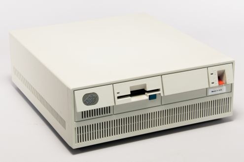 IBM PS/2 Model 50 (8550-021)
 -
 IBM PS/2 Model 50 Z
 -
 Model 50 Z with the cover off
 -
 Model 50 badge
 -
 Model 50 Z badge


References
[edit | edit source]- ↑ 1.0 1.1 1.2 1.3 1.4 1.5 1.6 1.7 1.8 IBM Announcement Letter 187-049, IBM Personal System/2 Model 50, 2 April 1987, text at ardent-tool.com. The 8550-021 at US$3,595; 10 MHz 80286; 1 MB on the system board, expandable to 7 MB; ROM BASIC; VGA with 640 × 480, 320 × 200 in 256 colours and 720 × 400 text; CBIOS and ABIOS totalling 128 KB; four 16-bit slots with one occupied by the disk controller; a 94 W automatic voltage-sensing supply; a battery-backed clock; room for a second diskette drive; and the 1.44 MB drive specification (80 tracks, 135 tpi, two heads, 500,000 bps, 6 ms track to track, 15 ms settle, 500 ms maximum motor start, 300 rpm ±1.5 %).
- ↑ 2.0 2.1 2.2 2.3 2.4 IBM Announcement Letter 188-080, IBM Personal System/2 Model 50 Z Desktop Systems with Improved Hardfile and Memory, 2 June 1988, text at ardent-tool.com. The 8550-031 at US$3,995 and 8550-061 at US$4,595; zero wait states with 85 ns memory; 1 MB standard, 2 MB on the system board with the 2 MB 85 ns kit, 16 MB maximum; 30 MB and 60 MB drives with integrated controller (25 and 26 sectors per track, 615 and 762 cylinders, 4 and 6 heads, 7.5 and 8.4 Mbit/s, 39 ms and 27 ms average access); three 16-bit slots; 94 W automatic voltage-sensing supply; DOS 3.30 and OS/2 Standard and Extended Editions.
- ↑ 3.00 3.01 3.02 3.03 3.04 3.05 3.06 3.07 3.08 3.09 IBM, IBM Personal System/2 Model 50 Technical Reference, May 1988. Hosted on this wiki as IBM PS2 Model 50 Technical Reference (May 1988) (PDF). Figure 1-6, "Performance Specifications – Type 2 System Board", p. 1-8; Figure 1-7, "Physical Specifications", p. 1-9 (size, weight, input ranges and current, 144.8 W heat output, 275 mA keyboard and 300 mA auxiliary port limits); "Real-Time Clock/Complementary Metal-Oxide Semiconductor RAM", p. 3-12.
- ↑ 4.0 4.1 IBM, "IBM PS/2 (Model 50) – Technical specifications", document GJAN-43VM6G (2000), mirrored at ardent-tool.com. One wait state; two 30-pin 512 KB parity modules at about 150 ns; three 3.5-inch half-height bays; 20 MB drive with 80 ms access.
- ↑ 5.0 5.1 5.2 5.3 5.4 5.5 IBM, IBM Personal System/2 Model 50 Technical Reference, October 1990. Hosted on this wiki as IBM PS2 Model 50 Technical Reference (October 1990) (PDF). Type 1 and Type 2 system boards and their model bytes, Figure 1-1, p. 1-3; power supply outputs, channel load currents and output protection, pp. 1-11 and 1-12; ROM and RAM subsystems, pp. 3-7 and 3-8; memory connectors, p. 3-9.
- ↑ 6.0 6.1 6.2 6.3 6.4 6.5 Louis Ohland, Tomáš Slavotínek et al., "8550 Planar", Ardent Tool of Capitalism. Designator map and photographs of planars 90X9161 and 15F6969, including F1 250 V 3 A, J1 battery/speaker connector, J9 fan, J10 fixed-disk adapter slot, J11 slot with auxiliary video extension, ZM47 MC146818A, Y3 32.768 kHz crystal and ZM13–ZM16 BIOS in four 27256 EPROMs; the Model 50/60 Reference Disk v1.08; and Peter Wendt's note that the 021 BIOS lacks the code for the integrated drives.
- ↑ 7.0 7.1 7.2 7.3 Louis Ohland, Tomáš Slavotínek et al., "8550 Z Planar", Ardent Tool of Capitalism. Designator map of planar FRU 90X9533, including F1 3 A 250 V, J2 battery/speaker header, J8 case fan header, ZM8 MC146818A, ZM45 72-pin SIMM socket, ZM49 P8042AH, ZM50 µPD765AC-2, ZM51 15F6864 VGA controller and BIOS in two 27512 EPROMs; 85 ns 1 or 2 MB memory with zero wait states.
- ↑ 8.0 8.1 8.2 8.3 8.4 8.5 IBM, IBM Personal System/2 Hardware Maintenance Manual, S52G-9971-02, October 1994. Hosted on this wiki as IBM Personal System 2 Hardware Maintenance Manual (S52G-9971-02, October 1994) (PDF). "Copy an option diskette" in the devices list, p. 23; Models 50 and 70 power supply connector, p. 141; Model 50 parts list, p. 240.
- ↑ 9.0 9.1 9.2 9.3 9.4 9.5 9.6 9.7 IBM, IBM PS/2 Model 50 Hardware Maintenance Reference, S64F-3989-00, March 1990. Hosted on this wiki as IBM PS2 Model 50 Hardware Maintenance Reference (PDF). Sections 1.0 (product description, 94 W automatically switching supply), 1.1.2 (power-on password), 1.2.2 (CMOS RAM), 1.2.4 (VGA and the extended slot), 1.2.7 (diskette-drive controller and bus adapter), 1.2.8 (keyboard and pointing-device connectors and fuse), 3.1 (power supply, sense levels and the power-good light), 3.2 (POST), 4.0 (specifications), 5.0 (snap tool 72X8547).
- ↑ Mitsubishi Electric, 3.5 inch Flexible Disk Drive Standard Specifications, MF355C, UGD-0527A, February 1987. Hosted on this wiki as File:Mitsubishi MF355C 3.5 inch Diskette Drive Specifications (UGD-0527A, Feb 1987).pdf. Section 3: brushless DC direct-drive spindle motor at 300 rpm.
- ↑ "8580 Diskette Drives", Ardent Tool of Capitalism, content by Fred Spencer and Al Savage. Al Savage's recap of Mitsubishi MF355W-99M3 card-edge drives (P/N 90X6766, FRU 72X8523), whose surface-mount electrolytics had gone open or very high ESR.
- ↑ 12.0 12.1 Louis Ohland, Tomáš Slavotínek et al., "8550 HDD Adapters", Ardent Tool of Capitalism. The early ST-506 adapter FRU 90X8070 and later 90X8642 for the 021's 20 MB drive; the bare riser FRU 90X9441, a passive interconnect; the riser with BIOS FRU 90X9571 used when a 60 MB drive was fitted to an 021; the IBM pocket-reference table of drives (72X8522 20 MB ST-506, WD325N; 6128287 30 MB "ST506 like", WD336RT; 6128294 "ESDI like", WD387); and Peter Wendt's explanation that the integrated drives are a Micro Channel controller and disk in one unit, not true ESDI.
- ↑ 13.0 13.1 Louis Ohland, Tomáš Slavotínek et al., "8550 / 8570 / 756x – Power Supply", Ardent Tool of Capitalism. The 50-pin connector pinout; the test-voltage table (−12 V −9.0 to −15.0 V at pins 2 and 1; +12 V +9.0 to +15.0 V at pins 2 and 3; +5 V +3.7 to +6.2 V at pins 2 and 15); the ASTEC AA13621 (IBM P/N 90X9527, FRU 90X9366) with its per-pin currents and 94 W maximum continuous output; the separate fan (Panaflo FBH-09A12L or Nidec D09B-12PLL); the T10 security Torx case screws; the removal procedure; and the note that F1 or F2 is the suspect in a supply with no output.
- ↑ Ardent Tool of Capitalism, "PS/2 RTC/CMOS Batteries", based on content by Bob Eager and Peter H. Wendt. Model 50 and 50 Z: FRU 72X8498, a 6 V two-cell lithium pack held in the battery/speaker assembly; equivalents CR-P2, DL223A, EL223AP, K223LA and PC223.
Related pages
[edit | edit source]- IBM PS/2 Model 50 Maintenance Guide
- IBM PS/2 Model 50 Troubleshooting Guide
- IBM PS/2 Model 50 Capacitor Replacement Guide
- IBM PS/2 Model 60
- IBM PS/2 Model 30, IBM PS/2 Model 70 and IBM PS/2 Model 80