

IBM System/23 Datamaster
 | |
| IBM System/23 Datamaster (5322) | |
| Specifications | |
|---|---|
| Manufacturer | IBM |
| Type | Small-business desktop computer |
| Released | July 1981[1] |
| CPU | Intel 8085[2] |
| Memory | 32, 64, 96 or 128 KB read/write storage with parity; 112 KB read-only storage (ROS)[3] |
| Storage | None, one or two internal 8-inch diskette drives (0.25 MB or 1 MB each)[4] |
| Display | Built-in 305 mm (12 in.) CRT, 24 lines of 80 characters[5] |
| Sound | — |
| Input | 83-key capacitive keyboard[5] |
| OS / Firmware | BASIC in read-only storage |
| Predecessor | IBM 5120 |
| Model no. | 5322 (models 110 to 144); 5324 (floor-standing unit) |
The IBM System/23 Datamaster is a small-business computer that IBM launched in July 1981.[1] The 5322 is a one-piece desk-top unit with an 8085 processor, a 12-inch monochrome display, the keyboard and up to two 8-inch diskette drives, programmed in BASIC.[2][5] A floor-standing 5324 followed in 1982. Several of the Datamaster's design elements, and some of its engineers, went on to the IBM Personal Computer.[2]
History
[edit | edit source]David Bradley, who wrote device-control code for the Datamaster and then the BIOS for the IBM PC, gives this account in BYTE:[2]
- The Datamaster programme began in February 1978. Bradley finished his work on it in August 1980, when he was moved to the twelve-person team that designed the IBM PC.
- During development IBM "converged" the Datamaster's BASIC with the BASIC of the IBM System/34, which delayed the Datamaster by nearly a year. The PC team drew the lesson that it should use an existing BASIC, and went to Microsoft.
- The 8085's 64 KB address space forced the Datamaster team to add an external paging mechanism to address at least 256 KB, and the project made them familiar with Intel's architecture and support chips. Bradley gives the 64 KB limit and that familiarity among the reasons the PC used the 8088.
- The one-piece design suited the System/23's business market but was too inflexible for a personal computer, so the PC was given a separate keyboard and display.
The IBM 5324 was announced in Europe in February 1982. IBM's announcement describes a floor-standing unit 660 mm high holding the processor, memory, power supply and optional diskettes, with a separate display module and keyboard module, and "all of the functions, features, and support of the previously announced System/23 processors". Plant shipments of the data-processing models (1xx) were to begin in April 1982 and of the data and word-processing models (4xx) in June 1982.[6]
Models
[edit | edit source]The 5322 model number encodes the storage size and the internal diskette configuration. The second digit gives the read/write storage (1 = 32K, 2 = 64K, 3 = 96K, 4 = 128K) and the third the diskette drives (0 = none, 1 = one drive and 0.25 MB, 2 = two drives and 0.5 MB, 3 = one drive and 1 MB, 4 = two drives and 2 MB, where MB means 1,000,000 bytes).[4]
| Storage | No drives | 1 drive, 0.25 MB | 2 drives, 0.5 MB | 1 drive, 1 MB | 2 drives, 2 MB |
|---|---|---|---|---|---|
| 32K | 110 | 111 | 112 | 113 | 114 |
| 64K | 120 | 121 | 122 | 123 | 124 |
| 96K | 130 | 131 | 132 | 133 | 134 |
| 128K | 140 | 141 | 142 | 143 | 144 |
The External Diskette Attachment feature, for the IBM 5246 Diskette Unit, is required on Models 110, 120, 130 and 140, which have no internal drives, and optional on the others. One or two 5322s can share a 5246 if it has the second port feature.[5]

Hardware
[edit | edit source]Processor and storage
[edit | edit source]The processor is an Intel 8085.[2] IBM's service manual does not name the chip; it describes a microprocessor with registers A to E, H and L, a 16-line address bus, DMA control, timers, interrupt control and storage page registers on the CPU planar board. The planar carries 112K of read-only storage (ROS), which holds the microprograms that interpret BASIC and control the I/O devices. Read/write storage of 32K to 128K, with parity generation and checking, is on circuit cards that plug into sockets on the planar.[3]
Display and keyboard
[edit | edit source]The CRT display unit has a 305 mm (12 in.) screen showing 24 lines of 80 characters (1,920 characters).[5] Bradley writes that the display is driven by an Intel 8275 CRT controller, and that the IBM PC's Monochrome Display Adapter was based on it but used a Motorola 6845 instead, because the 8275 could show only 128 characters and needed a character position for each attribute change.[2]
The keyboard has 83 keys over a capacitive matrix, scanned by a microprocessor on the keyboard card which sends a scan code and an interrupt request to the processing unit. The complete keyboard assembly is a single field-replaceable unit.[7]

Diskette drives
[edit | edit source]Two types of internal 8-inch drive were fitted. The 31SD has one read/write head and the 51TD two; they differ only in the head/carriage assembly and the drive control card. The drives turn at 360 rpm and use an AC drive motor.[8]
IBM's maintenance preface says the head/carriage assembly may be replaced in the field, but "do not repair or clean any part of this assembly". The only use of isopropyl alcohol near the heads is to remove old adhesive from the head load arm when fitting a new pressure pad on the 31SD drive.[8]
Power supply
[edit | edit source]The 5322 was built with either a ferroresonant supply or a transistor-switching-regulator (TSR) supply; IBM describes the two as functionally interchangeable. Both provide -5, +5, -12, +12 and +24 V DC and a 120 V AC output for the diskette motors, the CRT display unit and the fan. The power-good signal becomes active when the -5, +5, -12 and +12 V levels are within about 80 % of nominal, and an LED on the supply shows its state. Fuse F6 protects the AC input.[9]
DANGER: IBM warns that up to 800 V AC is generated in the power supply. Switch off and unplug the 5322 before removing the supply or any part of it.[10]
| Output | Fuse | Tolerance | Ripple, peak to peak |
|---|---|---|---|
| +5 V | F5, 10 A | +4.6 to +5.5 V | 0.12 V |
| -5 V | F1, 0.5 A | -4.6 to -5.5 V | 0.05 V |
| +12 V | F2, 1.5 A | +11.0 to +13.2 V | 0.175 V |
| -12 V | F3, 0.5 A | -11.0 to -13.2 V | 0.12 V |
| +24 V | F4, 1.5 A | +22.0 to +26.4 V | 0.325 V |
| Power good | +2.4 to +5.5 V | 0 |
IBM's tolerances apply to voltages measured at the power supply A1 card. Without an oscilloscope, IBM checks ripple with the CE meter on its 2.5 V AC range and a capacitor of 0.22 µF or more (50 V or higher) in series with one lead; if the pointer leaves zero, there may be excess ripple.[11] The fuse ratings are from the supply sections.[10]
Three supplies are documented: PN 6838279 (60 Hz, Canada and US), PN 6838280 (60 Hz, GBG/I) and PN 6838281 (50 Hz, GBG/I). The two GBG/I supplies have jumper-selected transformer taps for their input voltage, so check the taps before connecting an imported machine to the mains.[10]
Peripherals
[edit | edit source]- IBM 5241 (80 characters per second) and 5242 (160 cps; the Model 2 also prints at 40 cps in high-density mode) matrix printers. The first printer port is standard and a second is an optional feature.[5][6]
- IBM 5246 Diskette Unit: up to two drives of 1.1 MB each; models 021 and 022 can be shared by two computers.[6]
- Communications: asynchronous or binary synchronous (BSC), as an option.[6]
- IBM 5247 Disk Unit, with its own service manual (SY34-0243-0, April 1982).[12]
Diagnostics
[edit | edit source]The power-on diagnostic, PID 1200, is held in ROS and runs at every power-on for 25 to 35 seconds. Until the display is running, a failure stops the machine with an error code in hardware latches for the customer engineer to probe; afterwards the result of each routine is shown on the screen, with the display attribute giving the result. Jumpers on the CPU board make the test loop or stop on error. The IBM System 23 Diagnostic User Guide describes this and the diskette-based diagnostic programs.[13]
Links to the IBM PC
[edit | edit source]Bradley lists these as carried from the Datamaster to the IBM PC:[2]
- The keyboard design, among other design elements.
- The 62-pin expansion connector. The PC team kept its bus close to the Datamaster's because they already had adapter cards for it; the Datamaster used the same interrupt controller and a similar DMA controller, and the PC added address lines for the 8088. Bradley writes that "the final definition changed only five of the originally proposed signal lines".
- The Monochrome Display Adapter, based on the Datamaster display but redesigned around a 6845 controller.
- The practice of publishing hardware and software interface data, adopted because even IBM could not develop everything a personal computer needed.
Documentation
[edit | edit source]- IBM 5322 Computer Service Manual, SY34-0171-0 (December 1980), hosted here.
- IBM System 23 Diagnostic User Guide, PN 6841631 (April 1982), hosted here.
- On bitsavers (ibm/system23): the IBM 5324 Computer Service Manual (SY34-0241-1, May 1982), the IBM 5247 Disk Unit Service Manual (SY34-0243-0), the System/23 user manual binders (including the BASIC Language Reference, SA34-0109-1) and the ROS module datasheets.
- IBM 5324 Computer Service Manual
Gallery
[edit | edit source]-
 Datamaster 5322 front
 -
 Datamaster 5322 angle view
 -
 5322 computer
 -
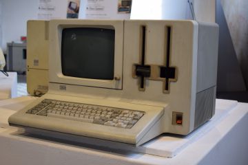 5322 full configuration
 -
 5322 alternate angle
 -
 5322 with the keyboard removed
 -
 5322 keyboard
 -
 CPU planar board, European version
 -
 CPU planar board (1983)
 -
 5324 floor-standing unit


Related pages
[edit | edit source]- IBM System/23 Datamaster Maintenance Guide, IBM System/23 Datamaster Troubleshooting Guide, IBM System/23 Datamaster Capacitor Replacement Guide
- IBM 5120, the earlier IBM small-business computer
- IBM PC (5150)
References
[edit | edit source]- ↑ 1.0 1.1 Wikipedia, "IBM System/23 Datamaster" (tertiary; it cites Cope and Gollings, Multilingual Book Production, 2001, p. 69, for the July 1981 launch).
- ↑ 2.0 2.1 2.2 2.3 2.4 2.5 2.6 Bradley, D. J., "The Creation of the IBM PC", BYTE, September 1990, pp. 414-418 (archive.org). Bradley wrote device-control code for the Datamaster before joining the IBM PC design team.
- ↑ 3.0 3.1 IBM 5322 Computer Service Manual, SY34-0171-0, pp. 2-41, 2-47 (CPU planar board functional data flow) and 2-48 (functional units).
- ↑ 4.0 4.1 IBM, IBM 5322 Computer Service Manual, SY34-0171-0, December 1980, p. 2-40, "5322 computer model numbers" (hosted here).
- ↑ 5.0 5.1 5.2 5.3 5.4 5.5 IBM 5322 Computer Service Manual, SY34-0171-0, pp. 2-40 and 2-41 (standard and optional features, external I/O devices).
- ↑ 6.0 6.1 6.2 6.3 IBM Product Information (Europe, Middle East and Africa), "IBM 5324 Computer announced", February 1982 (bitsavers text).
- ↑ IBM 5322 Computer Service Manual, SY34-0171-0, p. 3-16 (keyboard data flow).
- ↑ 8.0 8.1 IBM 5322 Computer Service Manual, SY34-0171-0, chapter 5: maintenance preface (p. 5-3), item 1531 (p. 5-29) and drive specifications (pp. 5-66 and 5-67).
- ↑ IBM 5322 Computer Service Manual, SY34-0171-0, p. 2-57, "Power supplies".
- ↑ 10.0 10.1 10.2 IBM 5322 Computer Service Manual, SY34-0171-0, items 1240, 1250 and 1260 (60 Hz US/Canada, 60 Hz GBG/I and 50 Hz GBG/I supplies: layout, removal and fuses).
- ↑ IBM 5322 Computer Service Manual, SY34-0171-0, item 1211, p. 2-11, "DC voltage distribution diagram".
- ↑ bitsavers, ibm/system23/5247 (IBM 5247 Disk Unit Service Manual, SY34-0243-0).
- ↑ IBM, Diagnostic User Guide 0001, System/23 with Diskette, PN 6841631, EC 327594 (April 1982), section 21, pp. 75-76 (hosted here).