

IBM PS/2 Model 60
 | |
 | |
| IBM PS/2 Model 60 (8560) | |
| Specifications | |
|---|---|
| Manufacturer | IBM |
| Type | Floor-standing personal computer |
| Released | 2 April 1987 |
| Intro price | US$5,295 (8560-041); US$6,295 (8560-071)[1] |
| CPU | Intel 80286 at 10 MHz, one wait state |
| Memory | 1 MB on the system board; 15 MB system maximum with memory adapters |
| Storage | 1.44 MB 3.5-inch diskette drive; 44 MB ST-506 (041) or 70 MB ESDI (071) fixed disk |
| Display | VGA on the system board, 256 KB video memory |
| Sound | Speaker |
| Dimensions | 165 × 483 × 597 mm (W × D × H); 318 mm wide with the feet extended[2] |
| Weight | 20 kg with one fixed disk[2] |
| OS / Firmware | IBM DOS 3.30; OS/2 Standard and Extended Editions |
| Codename | Rough Rider[3] |
| Model no. | 8560-041, 8560-071 |
The IBM Personal System/2 Model 60 (machine type 8560) is a floor-standing computer with a 10 MHz Intel 80286 and IBM's Micro Channel bus. IBM announced it on 2 April 1987, alongside the IBM PS/2 Model 30, IBM PS/2 Model 50 and IBM PS/2 Model 80, and described it as the "mid-range, desk-side" member of the family.[1] It has the Model 50's processor, memory speed and integrated VGA, in a tower with eight channel connectors, room for two fixed disks and a larger power supply. The same chassis and supply family were used for the Model 80 and later the Model 65 SX.[3][4]
IBM claimed that with the Micro Channel, its disk cache program and an 80287, the Model 60 could run up to twice as fast as a PC AT Model 339 with an 80287.[1]
Models
[edit | edit source]| Submodel | Price at launch | Memory | Fixed disk | Disk adapter | Power supply |
|---|---|---|---|---|---|
| 8560-041 | US$5,295 | 1 MB | 44 MB ST-506, 40 ms average access | ST-506 adapter | 207 W |
| 8560-071 | US$6,295 | 1 MB | 70 MB ESDI, 30 ms average seek | ESDI adapter | 225 W |
Sources: IBM's announcement letter and product specification sheet.[1][5] IBM planned availability for April 1987 (041) and the second quarter of 1987 (071). Programs identify the Model 60 by model byte FC and submodel byte 05.[1][2]
System board
[edit | edit source]The Model 60 planar is IBM FRU 72X8538; Ardent Tool records board part numbers 90X9159 and 90X8434.[6][7] It has 128 KB of ROM, 1 MB of RAM, 64 bytes of CMOS RAM with the real-time clock plus a 2 KB CMOS RAM extension, VGA with 256 KB of video memory, eight DMA channels, 16 level-sensitive interrupt levels, the keyboard and auxiliary-device controller with password security, a diskette controller for 720 KB and 1.44 MB media, a serial port with FIFO mode, a bidirectional parallel port and a socket for an 80287 running at the processor's clock.[2]
| Designator | Device |
|---|---|
| ZM128 | Intel 80286, 10 MHz |
| ZM134 | 80287 socket |
| ZM6 | Motorola MC146818A real-time clock and CMOS RAM |
| Y1 | 32.768 kHz crystal for the clock |
| ZM5 | NEC µPD446C-15L 2 KB static RAM (CMOS RAM extension) |
| ZM101, ZM111, ZM116, ZM118 | BIOS, four 27256 EPROMs |
| ZM15 | Intel P8742AH keyboard controller |
| ZM33 | NEC µPD765AC diskette controller |
| ZM35 | 72X8299 I/O controller |
| ZM61 | NS16550 UART |
| ZM55, ZM56 | 8259A interrupt controllers |
| ZM70 | 72X7385 bus controller |
| J25 | 72X7377 DMA controller |
| J10 | 72X8287 VGA controller |
| ZM87 | Inmos IMSG171 RAMDAC |
| ZM36, ZM37, ZM41, ZM42, ZM51, ZM52, ZM59, ZM60 | TI TMS4464 64K × 4 DRAM, the 256 KB of video memory |
| ZM43 to ZM46 | 30-pin memory sockets |
| ZM129 | LM386 speaker amplifier |
| J3 | Power supply connector (15-pin) |
| J14 | Battery and speaker assembly connector |
| J21 | Channel connector with the auxiliary video extension |
| J18, J19, J22, J24, J28, J29, J30 | Channel connectors |
| F1 | Keyboard and mouse fuse, 3 A 250 V |
Source: Ardent Tool's designator map.[7] A photograph of a 90X8434 board shows through-hole yellow dipped tantalum capacitors, surface-mount ceramic capacitors and resistor networks, and no aluminium electrolytic capacitors.[7]
Micro Channel
[edit | edit source]IBM's Technical Reference lists eight channel connectors with 8- or 16-bit device support, one with the auxiliary video extension and one occupied by the fixed-disk adapter, which leaves seven for other cards.[2][5] There are no 32-bit slots. IBM retain tip H005662 sets slot and interrupt rules for the 3270 Connection, Token-Ring and PC Network adapters in the 8560 and other Micro Channel models, and warns that Automatic Configuration resets their interrupt levels to the defaults unless the configuration has been backed up.[8]
Memory
[edit | edit source]The system board holds 1 MB in four 256 KB, 30-pin parity memory modules, which run with one wait state; their timing is like a 150 ns Hitachi HB61009BR-15. The first 640 KB is conventional memory and the other 384 KB is mapped at 1 MB.[2] IBM's FRU for the module is 61X8906.[6] Memory beyond 1 MB goes on Micro Channel adapters. The 80286 Memory Expansion Option carries 512 KB and takes up to three 512 KB kits, for 2 MB per card; seven of them bring the machine to IBM's 15 MB maximum.[1]
Video
[edit | edit source]The VGA is on the system board, with 256 KB of video memory. It supports 640 × 480 graphics, 320 × 200 in 256 colours and 720 × 400 text, and is compatible with CGA and EGA modes.[1][2] One channel connector carries the auxiliary video extension for adapters that work with the on-board VGA. Ardent Tool warns that some non-IBM graphics adapters drive VGA signals instead of receiving them, and that two adapters driving VGA signals in one machine damage each other.[9]
Storage
[edit | edit source]Diskette
[edit | edit source]The machine ships with one 1.44 MB 3.5-inch drive and has a position for a second.[1] IBM's 1994 FRU numbers are 72X8523 for the half-height drive and 64F0162 for the later third-height drive.[6] These drives take power and signals through one connector and are direct drive, with no belt.[10][11] Their best-known fault is failed surface-mount electrolytic capacitors on the drive board.[10]
Fixed disk
[edit | edit source]The fixed disks are 5.25-inch full-height drives on a separate adapter card, with a control cable, a signal cable per drive and a 4-pin power lead.[5][6]
| Submodel | Drive (IBM FRU) | Adapter (IBM FRU) | Geometry and timing |
|---|---|---|---|
| 8560-041 | 44 MB ST-506, 72X8541 | ST-506 fixed disk adapter, 72X8540 | 733 cylinders, 17 sectors per track, 512-byte sectors; 5 Mbit/s; 10 ms track to track, 40 ms average, 80 ms maximum |
| 8560-071 | 70 MB ESDI, 72X8519 | ESDI fixed disk adapter, 92F0061 | 583 cylinders, 36 sectors per track, 512-byte sectors; 10 Mbit/s; 5 ms single cylinder, 30 ms average seek, 60 ms maximum |
Sources: IBM's announcement letter and 1994 parts list.[1][6] The 115 MB ESDI drive (FRU 90X7392) was announced with the Model 60 for the 071, and IBM later listed a 314 MB ESDI drive (90X8745) and SCSI drives for the 60, 65 and 80 chassis.[1][6]
IBM retain tip H064300 says that a 1780 at POST on an 8560-041 means checking that the fixed-disk cables are fitted correctly.[9]
Power supply
[edit | edit source]The Model 60 uses IBM's Type 2 supply: an automatic voltage-sensing unit with three outputs, +5 V, +12 V and −12 V, a 15-pin connector to the system board and two 4-pin connectors for the fixed disks.[2][12][1] The 041 was fitted with a 207 W supply and the 071 with a 225 W supply.[5] IBM's 1994 parts list gives one replacement for all Models 60, 65 and 80, FRU 57F1600, which Ardent Tool lists as a 250 W unit.[6][4]
A short on any output, or an internal overvoltage fault before any output reaches 130 % of nominal, latches all outputs off. The supply restarts only after the fault is removed and the power switch has been off for at least ten seconds. The green front LED shows that the supply is running; the yellow LED shows fixed-disk activity.[12] The 225 W unit 72X6665 is drawn in Eric Schlaepfer's reverse-engineered schematic, which is hosted here. In that unit the green LED is driven from Power Good, and a transistor in the supply drives the disk LED from a signal the system board sends on pin 15 of the power connector.[13][4]
IBM's 1994 test limits for the Models 60, 65 and 80, measured with the negative lead on pin 2 of the system-board connector or pin B of a drive connector:[6]
| Output | + lead | Minimum | Maximum |
|---|---|---|---|
| −12 V | P2 pin 9 | −9.0 V | −15.0 V |
| +12 V | P2 pin 3 | +9.0 V | +15.0 V |
| +5 V | P2 pin 1 | +3.7 V | +6.2 V |
| +5 V | Drive connector pin D | +3.7 V | +6.2 V |
| +12 V | Drive connector pin A (− lead on pin C) | +9.0 V | +15.0 V |
Ardent Tool's copy of the table adds that the 15-pin connector should be unplugged from the system board before taking the drive-connector readings.[4] The supply rectifies the mains, and its reservoir capacitors hold a dangerous charge after it is unplugged; see IBM PS/2 Model 60 Capacitor Replacement Guide before opening one.
Other figures from the Technical Reference: heat output 363.4 W; input 90–137 V or 180–265 V AC at 50–60 Hz ±3 Hz; maximum current 5.3 A on the low range or 2.7 A on the high range; maximum load 275 mA on the keyboard port and 300 mA on the auxiliary device port.[2]
Clock and battery
[edit | edit source]The clock is a Motorola MC146818A on the planar (ZM6), with a 32.768 kHz crystal.[7] A 6 V lithium battery keeps it and the 2 KB CMOS RAM extension running when the supply is off, and the cover lock stops the battery being removed to clear the password and configuration.[2] The battery is IBM part 72X8498, in the battery and speaker assembly 33F5950, which plugs into J14.[6][7] IBM retain tip H024809, reproduced by Ardent Tool, links intermittent 161, 162 and 163 errors to low battery voltage and says to replace the battery if it reads below 5.5 V DC out of the assembly.[9] The test, the pack's camera-battery equivalents and the power-on password override are in the maintenance guide.
Chassis
[edit | edit source]The tower is 165 mm wide (318 mm with the feet turned out), 483 mm deep and 597 mm high, and weighs 20 kg with one fixed disk; IBM's later specification sheet gives 21.3 kg. The power cable is 1.8 m and the keyboard cable 3.05 m.[2][5] There are bays for two 3.5-inch half-height diskette drives and two 5.25-inch full-height drives.[5] The side cover is held by two captive screws; the cover lock is at the top.[9]
Ardent Tool's contributors report that the area of the planar under the supply fan collects conductive dust. On the Model 80 that area holds the keyboard controller, the clock and CMOS RAM, the diskette controller, the serial controller and the clock crystal, and the dust causes lost configuration, a wrong clock and diskette errors that a new battery does not cure.[9][10]
BIOS and Reference Diskette
[edit | edit source]The BIOS is 128 KB in four 27256 EPROMs, split into a compatibility BIOS (CBIOS) that addresses up to 1 MB and an advanced BIOS (ABIOS) for multitasking operating systems that addresses up to 16 MB. ROM BASIC is included.[1][7] There is no setup program in ROM. Configuration is set from the Reference Diskette, and the Model 50 and Model 60 share one; Ardent Tool hosts version 1.08.[7] Before fitting a new adapter, copy its files from the adapter's option diskette onto the backup Reference Diskette with Copy an option diskette.[6]
Upgrades
[edit | edit source]IBM's 1994 manual lists three processor upgrades for the Model 60: a 486SLC2 processor upgrade card for the Models 50 and 60 (FRU 71G2625), and 486DLC2 and 486DX2 system boards for the Models 60, 65 and 80 (FRUs 71G2610 and 71G2643). An upgraded machine should carry a Px label beside the serial number.[6]
Documentation
[edit | edit source]- IBM PS2 Model 60 Technical Reference (May 1988): IBM's hardware reference for the Model 60 (system board, POS registers, memory, RT/CMOS RAM, specifications).
- IBM Personal System 2 Hardware Maintenance Manual (S52G-9971-02, October 1994): the Micro Channel checkout and error codes, voltage checks, system board locations (p. 200) and the Models 60, 65 and 80 parts list (pp. 251–253).
- IBM PS/2 Hardware Interface Technical Reference (May 1988): the Type 2 power supply and the devices common to PS/2 machines.
- 225 W supply 72X6665, reverse-engineered schematic (Eric Schlaepfer, 2024).
General maintenance
[edit | edit source]Opening the tower, cleaning, the battery test and power-supply checks are in the IBM PS/2 Model 60 Maintenance Guide.
Troubleshooting
[edit | edit source]Beep codes, the clock and battery errors, fixed-disk errors and the dead-system procedure are in the IBM PS/2 Model 60 Troubleshooting Guide.
Capacitor replacement
[edit | edit source]Ardent Tool's photograph of a 90X8434 planar shows no aluminium electrolytics. The 225 W supply and the diskette drive boards are covered in the IBM PS/2 Model 60 Capacitor Replacement Guide.
Gallery
[edit | edit source]-
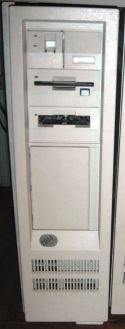 IBM PS/2 Model 60 (8560)
 -
 Model 60 front badge
Related pages
[edit | edit source]- IBM PS/2 Model 60 Maintenance Guide
- IBM PS/2 Model 60 Troubleshooting Guide
- IBM PS/2 Model 60 Capacitor Replacement Guide
- IBM PS/2 Model 50
- IBM PS/2 Model 80
References
[edit | edit source]- ↑ 1.00 1.01 1.02 1.03 1.04 1.05 1.06 1.07 1.08 1.09 1.10 1.11 IBM Announcement Letter 187-050, IBM Personal System/2 Model 60, 2 April 1987, text at ardent-tool.com. Prices US$5,295 (041) and US$6,295 (071); 10 MHz 80286; ROM BASIC; 1 MB on the system board, expandable to 15 MB; CBIOS and ABIOS totalling 128 KB; VGA modes; eight 16-bit slots with one used by the disk controller; automatic voltage-sensing universal supply; battery-backed clock; positions for a second 5.25-inch fixed disk and a second 3.5-inch diskette drive; the 44 MB and 70 MB drive specifications; the 80286 Memory Expansion Option (512 KB, up to three 512 KB kits, up to seven options for 15 MB); IBM's performance claim against the PC AT Model 339; DOS 3.30 disk cache; OS/2 Standard and Extended Editions support for the 80286 Expanded Memory Adapter/A.
- ↑ 2.00 2.01 2.02 2.03 2.04 2.05 2.06 2.07 2.08 2.09 2.10 IBM, IBM Personal System/2 Model 60 Technical Reference, May 1988. Hosted on this wiki as IBM PS2 Model 60 Technical Reference (May 1988) (PDF). Model and submodel bytes, p. 1-3; Figure 1-1, "System Board Devices and Features", p. 1-4 (eight channel connectors, Type 2 power supply); Figure 1-5, "Physical Specifications", p. 1-8; ROM and RAM subsystems, p. 3-7; memory map, p. 3-8; memory connectors, p. 3-9; "Real-Time Clock/Complementary Metal-Oxide Semiconductor RAM", p. 3-10.
- ↑ 3.0 3.1 Ardent Tool of Capitalism, "PS/2 Models 60, 65 SX, and 80". Types 8560, 8565 and 8580 share common devices and power supply; Model 60 code name "Rough Rider", Model 80 "Wrangler".
- ↑ 4.0 4.1 4.2 4.3 Ardent Tool of Capitalism, "60, 65 SX, and 80 – Power Supply". Removal procedure; planar power connector pinout (pins 1, 4, 7, 10, 13 +5 V; 3 +12 V; 9 −12 V; 12 Power Good; 15 hard-disk LED); test-voltage table; supply variants (225 W FRU 15F6548; 242 W; 250 W FRU 57F1600), "the same form factor and pinout for all 8560, 8565, and 8580 models", "the 8560 models are either 207 watts or 225 watts"; label of the 225 W unit 72X6665 (REV A58491, PEC 3978): 100–125 V 4.5 A or 200–240 V 2.5 A input, +12 V 7 A, +5 V 27.25 A, −12 V 0.39 A; Peter Wendt on power-switch failures; Fred Spencer's table of original fixed-disk power (44 MB and 70 MB: 31–39 W) from the IBM Personal System/2 Reference Guide.
- ↑ 5.0 5.1 5.2 5.3 5.4 5.5 IBM, "IBM PS/2 (Model 60) – Technical specifications", document GJAN-43VS3S (2000), mirrored at ardent-tool.com. 10 MHz with one wait state; eight slots, seven available; four 30-pin 256 KB modules at about 150 ns; 207 W (041) and 225 W (071) supplies, 110–220 V automatic; 21.3 kg; two 3.5-inch half-height and two 5.25-inch full-height bays; 44 MB drive on an ST-506 adapter and 70 MB drive on an ESDI adapter; PC DOS 3.30 or higher.
- ↑ 6.00 6.01 6.02 6.03 6.04 6.05 6.06 6.07 6.08 6.09 6.10 IBM, IBM Personal System/2 Hardware Maintenance Manual, S52G-9971-02, October 1994. Hosted on this wiki as IBM Personal System 2 Hardware Maintenance Manual (S52G-9971-02, October 1994) (PDF). Devices list and "Copy an option diskette", p. 23; processor upgrades and Px labels, pp. 136–137; Models 60, 65, 80 power supply check, p. 142; Model 60 system board locations, p. 200; Models 60, 65 and 80 parts (system board 72X8538, 256 KB memory kit 61X8906, battery/speaker assembly 33F5950, battery 72X8498, fuse 72X8561, power supply 57F1600, drives and adapters), pp. 251–253.
- ↑ 7.0 7.1 7.2 7.3 7.4 7.5 7.6 Ardent Tool of Capitalism, "8560 Planar". Designator map and photographs of planar FRU 72X8538 (P/N 90X9159 or 90X8434); Model 50/60 Reference Disk v1.08; ROM images 90X6815 to 90X6818 (27256 EPROMs, dated 13 February 1987).
- ↑ Ardent Tool of Capitalism, "Known Problems – Experience, RETAIN Tips, ECAs". IBM retain tip H005662 on the 3270 Connection, Token-Ring and PC Network adapters in the 8550, 8555, 8560, 8565, 8570, 8580 and 9585; Peter Wendt on hard-disk stiction.
- ↑ 9.0 9.1 9.2 9.3 9.4 Ardent Tool of Capitalism, "60, 65 SX, and 80 – Common Devices". Opening the case and removing the front bezel; opening a locked unit; IBM retain tip H064300 (1780 on the 8560-041 and 8580-041: check the fixed-disk cables); dust under the supply fan causing lost configuration, clock and disk errors; IBM retain tip H024809 (battery 72X8498, assembly 33F5950, replace below 5.5 V DC); ALPS and Mitsubishi diskette drives; the on-board VGA warning.
- ↑ 10.0 10.1 10.2 Ardent Tool of Capitalism, "8580 Diskette Drives", content by Fred Spencer and Al Savage. Card-edge drives P/N 90X6766, FRU 72X8523, made by Mitsubishi, Alps and Sony, and pin-style drives FRU 64F0162; power taken from the interface; the diskette controller under the supply fan collecting dirt and causing 6xx errors; Peter Wendt on the causes of a 162 from the drive; Al Savage's recap of the Mitsubishi MF355W-99M3.
- ↑ Mitsubishi Electric, 3.5 inch Flexible Disk Drive Standard Specifications, MF355C, UGD-0527A, February 1987. Hosted on this wiki as File:Mitsubishi MF355C 3.5 inch Diskette Drive Specifications (UGD-0527A, Feb 1987).pdf. Section 3: brushless DC direct-drive spindle motor at 300 rpm.
- ↑ 12.0 12.1 IBM, IBM Personal System/2 Hardware Interface Technical Reference, May 1988. Hosted on this wiki as File:IBM PS2 Hardware Interface Technical Reference May88.pdf. Section "Power Supply (Types 1 and 2)", pp. 1–5 (PDF pp. 578–582): three outputs; internal input fuse; ground leakage under 500 µA; output protection; voltage sequencing; no-load operation; green and yellow front LEDs; Type 2 15-pin system-board connector and 4-pin fixed-disk connectors.
- ↑ Eric Schlaepfer ("Tube Time"), IBM PS/2 Model 80 Power Supply reverse-engineered schematic, IBM P/N 72X6665, PEC 3978, 2024, CC BY-SA 4.0. Hosted on this wiki as File:IBM PS2 225W Power Supply 72X6665 Reverse-Engineered Schematic (Tube Time 2024).pdf; design notes at github.com/schlae/ps2-80-power.