

IBM PC (5150) Capacitor Replacement Guide
The IBM PC (5150) system board and IBM's expansion cards are decoupled with tantalum capacitors, and these can fail short-circuit. A shorted tantalum overloads the power supply, which shuts down all its outputs while an overload lasts, so the machine appears dead, although the supply fan may still turn.[1][2] Minuszerodegrees reports that the failure rate is high for tantalums that have been left unpowered for years and low for machines powered every few months.[2]
IBM's Technical Reference has logic diagrams of each system board but no parts list or placement drawing. The diagrams draw the filter capacitors between each supply line and ground, so they give the count on each line; the 1981 edition covers the 16KB-64KB board and the 1984 edition the 64KB-256KB board.[3][4] The positions on the board and the board photographs below are from minuszerodegrees.net, read from real boards. IBM published no circuit diagram of the 5150 power supply.[5]
Visual inspection and failure signs
[edit | edit source]
A failed tantalum may show a small black eye or hole in its body, as in the photograph, and some fail dramatically, with a shower of sparks or by exploding. Many failed tantalums show no sign at all, so a capacitor that looks intact is not proven good.[2] Minuszerodegrees finds that a tantalum that is going to fail usually does so when power is applied or within about 30 seconds.[2] Wear eye protection the first time an unknown board is powered.
Not every orange component on these boards is a tantalum; some are ceramic capacitors.[2]
IBM 5150 system board tantalum capacitors
[edit | edit source]The tantalums fitted to 51xx boards and cards are commonly 10 µF 16 V, marked "106 16V" or "10µF 16V".[2] IBM's 1981 diagram gives 8.2 µF for the early board's tantalums, and the 1984 diagram gives no value.[3][4] Minuszerodegrees describes the system board tantalums as all designated C7.[6] IBM's 1984 diagram labels all thirteen on the later board C7, but its 1981 diagram labels the six on the early board's ±12 V lines C6 and the eleven on its ±5 V lines C7. The 1984 diagram also draws 23 unpolarised capacitors, designated C3, from +5 V to ground.[3][4]
| System board | Tantalums | On +5 V | On −5 V | On +12 V | On −12 V |
|---|---|---|---|---|---|
| 16KB-64KB | 17 | 6 | 5 | 5 | 1 |
| 64KB-256KB | 13 | 10 | 1 | 1 | 1 |
The totals and the counts on each line agree between IBM's diagrams and minuszerodegrees, with one drafting fault: IBM's 1984 sheet draws four of the ten +5 V capacitors joined to the −5 V line with the positive side towards it, which cannot be right for a polarised part, and minuszerodegrees traced all ten to +5 V.[4][3][6] Minuszerodegrees identifies and photographs the positions on the +5 V, +12 V and −12 V lines but not those on −5 V, which are known only from IBM's diagrams.[6][7][8]
+5 V tantalum capacitors, 16KB-64KB board
[edit | edit source]Six of the seventeen tantalums on the early board are on the +5 V line.[6]

More than 95 % of the components on the board use +5 V and any of them can cause a short there, but a failed tantalum is the likeliest cause. If none shows a visible sign, remove the +5 V tantalums one at a time, checking after each whether the short has gone.[6]
+5 V tantalum capacitors, 64KB-256KB board
[edit | edit source]Ten of the thirteen tantalums on the later board are on the +5 V line. The same approach applies.[6]

+12 V and −12 V tantalum capacitors, 16KB-64KB board
[edit | edit source]On the early board the +12 V line feeds all the RAM chips and five tantalums. Any of them can short, but failure history points to the capacitors. Four of the five are grouped together and matter to the operation of the RAM, so a failed one must be replaced; minuszerodegrees recommends replacing all five with new 10 µF 16 V parts.[7]

The −12 V line on this board has one component, a tantalum, which is not critical; the board runs without it. When hunting a short on the ±12 V lines, minuszerodegrees removes this capacitor first because it is the only part on its line.[8]
+12 V and −12 V tantalum capacitors, 64KB-256KB board
[edit | edit source]On the later board the +12 V line has one component, a tantalum, and the −12 V line has one, also a tantalum. Both filter only the supply to the expansion slots, so neither is critical and the board runs without them. If there is a short on +12 V it is almost certainly the +12 V capacitor. Cutting it off gets the board running (though in rare cases the supply then needs more load than the board alone), and fitting a replacement is the recommended repair.[7][8]

Polarity and footprint
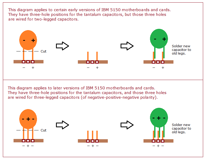
[edit | edit source]Every tantalum position on an IBM 51xx board or card has three holes, but they are wired two ways.[9][10]
- Early 5150 system boards and cards have three-hole positions wired for a two-legged capacitor, with the legs in the outer holes. They are not designed for three-legged parts. Put the positive leg in the hole marked + on the silkscreen.
- Later 5150 system boards and cards are wired for three-legged capacitors of negative-positive-negative polarity, whatever rail the capacitor is on. The centre hole is positive.
A three-legged replacement must also be negative-positive-negative; it can then be fitted either way round. Minuszerodegrees names Kemet T398E106M016AT (Mouser 80-T398E106M16AT). A two-legged capacitor can replace a three-legged one if its positive leg goes in the centre hole.[9]

Soldering technique
[edit | edit source]Minuszerodegrees warns that soldering on the 5150 board's ground and power lines is difficult and can damage the board, and suggests a technique it calls SNCTOL, "solder new capacitor to old legs":[7][10]
- Cut the old capacitor off above the board, leaving its legs soldered in the holes.
- Solder the new capacitor to the old legs, keeping the same polarity.
This may not be possible where the old capacitor sits hard against the board with no leg left to graft onto; then it has to be desoldered.[10]

Replacement parts
[edit | edit source]Replace with 10 µF tantalums rated 16 V or higher; minuszerodegrees gives 25 V as an example of a higher rating.[9] For three-legged positions, use a negative-positive-negative part such as the Kemet T398E106M016AT, or a two-legged part with its positive leg in the centre hole.[9]
Capacitor replacement procedure
[edit | edit source]- Switch off and unplug the machine. Remove the system unit cover; IBM's parts catalogue lists five system cover screws for the 5150.[11]
- Unplug P8 and P9 from the system board, remove the expansion cards and label the drive cables.
- Photograph the board before removing anything.
- Replace the tantalums one position at a time, using SNCTOL where possible and observing the polarity rules above.
- Clean off flux residue and check for solder bridges.
- Reassemble and power up with only the video card fitted; check the rails (see below) before refitting the other cards.
Finding a short-circuit tantalum
[edit | edit source]Minuszerodegrees' minimum diagnostic configuration isolates a short to the system board, a card or the supply:[12]
- Leave only the system board, power supply and speaker connected: no cards, no keyboard and no drives. Set SW1 switches 5 and 6 both off.
- Switch on. After about five seconds a working board gives one long and two short beeps (there is no display card). If it does, the board and supply are working and the fault is on a card, drive or keyboard; refit them one at a time.
- If there are no beeps and the fan does not run, or runs only for a moment, switch off, unplug P8 (which carries +12 V and −12 V to the board) and switch on again. If the fan now runs, the short is on the ±12 V lines: work through the ±12 V tantalums described above.[8]
- If the fan still does not run with P8 unplugged, the fault is either the supply or a short on the +5 V or −5 V lines. Unplugging P9 as well does not help, because the supply will not start without a load. On a 5150 with the IBM 63 W supply, test the supply with a full-height Tandon drive as its only load. If it starts, the supply is probably good and the short is likely on the board's +5 V or −5 V lines, although some supplies will not start even with the drive.[12]
Leave the supply off for at least five seconds before switching it on again. IBM's supply generates its Power Good signal only after five seconds off, and a quicker cycle can leave the board looking dead for an unrelated reason.[1]
Expansion card capacitors
[edit | edit source]IBM's cards use the same 10 µF 16 V tantalums and the same three-hole positions, wired for two or three legs depending on the card's age; the IBM EGA card is one reported case of failure.[2][10] On the IBM CGA card, tantalum C8 (10 µF 16 V) has a history of going short and stopping the machine from powering on. C8 and C9 filter only the +12 V to the card's Berg connectors P1 and P2, so if nothing is connected to them a failed C8 can be cut off and left out.[13]
If the system board runs on its own but the supply shuts down when a particular card is fitted, the short is on that card.[12]
Power supply capacitor replacement
[edit | edit source]Opening the supply exposes mains voltage. The red power switch does not remove mains from every part inside, and the large filter capacitors hold a dangerous charge after the supply is unplugged. Most, but not all, supplies have a bleeder resistor; measure the capacitor voltage with a meter before touching anything.[14][15]
IBM rates the supply at 63.5 W.[1] Units for 110 V are usually labelled 63.5 W and units for 220 V 63 W.[15] IBM's parts catalogue lists the 120 V supply as FRU 8529155 and the 220/240 V supply as 8654269.[11]
IBM published no circuit diagram of the supply, and the design varied during production (120 V and 220 V versions, AC and DC fans, and possibly more). Minuszerodegrees links two diagrams: one variation from a Sams COMPUTERFACTS document, and a 220 V Glesham Lion PLC type 32075 unit, also labelled 8529342.[5] There is therefore no single capacitor list for the 5150 supply. Read the values off the capacitors in the unit in front of you and replace like for like, with an equal or higher voltage rating.
The line suppression capacitors on the mains input tend to rupture with age; RIFA parts fail with smoke and a strong smell. Replace them with parts of the same capacitance, the same or higher AC working voltage, and the same safety class (X2 for X2, Y2 for Y2).[2]
Post-recap voltage checks
[edit | edit source]The supply needs a load to start; a working system board alone is normally enough, but not always.[15] Measure at the system board power connector with the board connected and running. IBM's service manual gives these limits:[16]
| Signal | Meter − lead | Meter + lead | Reading |
|---|---|---|---|
| Power Good | Pin 5 | Pin 1 | +2.4 to +5.25 V |
| +5 V | Pin 5 | Pin 10 | +4.8 to +5.25 V |
| −5 V (leads reversed) | Pin 9 | Pin 6 | +4.5 to +5.40 V |
| +12 V | Pin 7 | Pin 3 | +11.52 to +12.60 V |
| −12 V (leads reversed) | Pin 4 | Pin 8 | +10.80 to +12.96 V |
The Technical Reference gives the design regulation as +5 % / −4 % on +5 V and +12 V, +10 % / −8 % on −5 V and +10 % / −9 % on −12 V. Power Good has a 100 ms turn-on delay after the outputs reach their sense levels. The supply shuts down all outputs if +5 V or +12 V exceeds 200 % of its maximum rated voltage, and turns off if any output exceeds 130 % of its nominal current. It gives no ripple limit.[1]
References
[edit | edit source]- ↑ 1.0 1.1 1.2 1.3 IBM, Technical Reference, Personal Computer Hardware Reference Library, Revised Edition (April 1984), 6322507, Section 3 "Power Supply", pp. 3-3 to 3-6. Hosted as File:IBM PC 5150 Technical Reference.pdf, described at IBM PC 5150 Technical Reference.
- ↑ 2.0 2.1 2.2 2.3 2.4 2.5 2.6 2.7 Commonly Failing Electronic Components (in vintage computers), minuszerodegrees.net, sections "Tantalum Capacitor" and "Line Suppression Capacitor".
- ↑ 3.0 3.1 3.2 3.3 IBM, Technical Reference, Personal Computer Hardware Reference Library, First Edition (August 1981), 6025008, Appendix D, "System Board (I/O Channel)", p. D-11: the filter capacitors of the 16KB-64KB board, C6 on the ±12 V lines and C7 on the ±5 V lines, with a note giving all of them as 8.2 µF tantalum. Hosted as File:IBM PC 5150 Technical Reference (August 1981).pdf, described at IBM PC 5150 Technical Reference (August 1981).
- ↑ 4.0 4.1 4.2 4.3 IBM, Technical Reference, Revised Edition (April 1984), 6322507, "64/256K System Board (10 of 10)", p. 1-46: thirteen polarised capacitors designated C7 and 23 unpolarised capacitors designated C3, without values. Hosted as File:IBM PC 5150 Technical Reference.pdf.
- ↑ 5.0 5.1 IBM 5150 – Circuit diagram for IBM 63W power supply unit (PSU), minuszerodegrees.net.
- ↑ 6.0 6.1 6.2 6.3 6.4 6.5 Short-circuit on the +5 volt line of an IBM 5150/5155/5160 motherboard, minuszerodegrees.net.
- ↑ 7.0 7.1 7.2 7.3 Short-circuit on the +12 volt line of an IBM 5150/5155/5160 motherboard, minuszerodegrees.net.
- ↑ 8.0 8.1 8.2 8.3 Minuszerodegrees.net, minimum diagnostic configuration, pages for a short on the ±12 V lines: 16KB-64KB board and 64KB-256KB board.
- ↑ 9.0 9.1 9.2 9.3 Tantalum capacitors on IBM 51xx motherboards/cards, minuszerodegrees.net, with its pages for 2-legged and 3-legged wiring.
- ↑ 10.0 10.1 10.2 10.3 Minuszerodegrees.net, SNCTOL diagram for IBM 5150 motherboards and cards.
- ↑ 11.0 11.1 IBM, Hardware Maintenance Service, 6280087 (1986), Parts Catalog (PC, XT, Portable PC), Assembly 4 "System Unit – Interior (5150)", p. 10. Hosted as File:IBM Hardware Maintenance Service 6280087 Parts Catalog (PC, XT, Portable PC).pdf.
- ↑ 12.0 12.1 12.2 IBM 5150/5155/5160 – Minimum Diagnostic Configuration, minuszerodegrees.net, and the pages it leads to.
- ↑ IBM CGA Card – Capacitor C8 and IBM 5150/5160 cards, minuszerodegrees.net.
- ↑ IBM 51xx PC Family Computers – Some Hazards Within, minuszerodegrees.net.
- ↑ 15.0 15.1 15.2 IBM 5150 – Power Supply Unit (PSU), minuszerodegrees.net.
- ↑ IBM, Hardware Maintenance and Service, First Edition (August 1981), 6025072, power problem isolation chart pp. 020-5 to 020-7. Hosted as File:IBM PC 5150 Hardware Maintenance and Service (August 1981).pdf.
Related pages
[edit | edit source]- IBM PC (5150)
- IBM PC (5150) Maintenance Guide
- IBM PC (5150) Troubleshooting Guide
- IBM PC XT Capacitor Replacement Guide
- Capacitor Failure Symptoms