

IBM PC XT Capacitor Replacement Guide
The IBM PC XT (5160) system board carries through-hole tantalum capacitors that fail short-circuit. When one does, the power supply shuts down, because IBM designed it to switch off all outputs while a DC overcurrent exists, so a single failed 10 µF part makes the machine look dead, often with the fan still turning.[1][2]
The counts, photographs and procedures here come from minuszerodegrees.net, which has documented 5150/5160 system board failures for many years, checked against the filter capacitors on IBM's own logic diagrams. IBM did not publish a circuit diagram of the XT power supply.[3]
Visual inspection and failure signs
[edit | edit source]
A failed tantalum may show a small black hole on its body, a cracked or scorched case, or damage to a neighbouring part; some fail violently.[4] Often there is no visible sign at all, and the faulty part has to be found by measurement.[5]
minuszerodegrees.net reports that failures happen mostly at switch-on or within about thirty seconds of it, and mostly on boards that have not been powered for years.[4] Wear glasses for the first power-up of an unknown board.[2]
IBM 5160 system board tantalum capacitors
[edit | edit source]Both versions of the 5160 board carry sixteen tantalum capacitors, thirteen of them on the +5 V line.[6] IBM's logic diagrams show one 10 µF polarised capacitor with a 0.047 µF partner on each of the other three rails:[1]
| Rail | 10 µF polarised | 0.047 µF |
|---|---|---|
| +12 V | C56 | C55 |
| −12 V | C58 | C57 |
| −5 V | C68 | C67 |
| +5 V | C3, C10–C10 (range misprinted), C19, C28, C37, C46, C54, C60, C61, C63 | Many; the lists differ between the two boards |
The +5 V list is printed as shown on both board versions' diagrams, with a range that cannot be right; minuszerodegrees.net's photograph marks the thirteen positions on the board.[1][6] IBM prints the small value as ".047 PF". The replacement for every 10 µF position is 10 µF rated at 16 V or more.[7]
The −12 V line feeds nothing on the system board; it only goes to the expansion slots.[8]
+5 V tantalum capacitors
[edit | edit source]
Over 95 % of the components on the board use +5 V, so any of them could be the short, though a tantalum is the usual cause. If none shows a mark, minuszerodegrees.net removes them one at a time, checking after each whether the short has gone.[6]
+12 V: C55 and C56
[edit | edit source]C55 is a ceramic and can short, but C56 is the known failure; minuszerodegrees.net's failure history records it repeatedly.[5][9]

C56 filters only the +12 V going to the expansion slots, so the board works without it. Once it is confirmed shorted, it can be cut out and the board run as it is (in rare cases the supply then needs more load than the bare board), or replaced with a new 10 µF 16 V part, which minuszerodegrees.net recommends.[5] If the +12 V short remains with C56 removed, C55 is the only other part on that line.[5]
Polarity and footprint
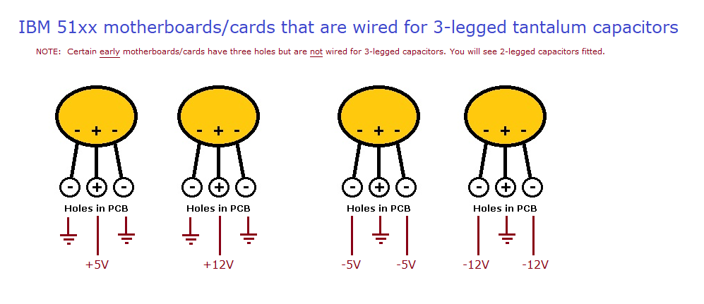
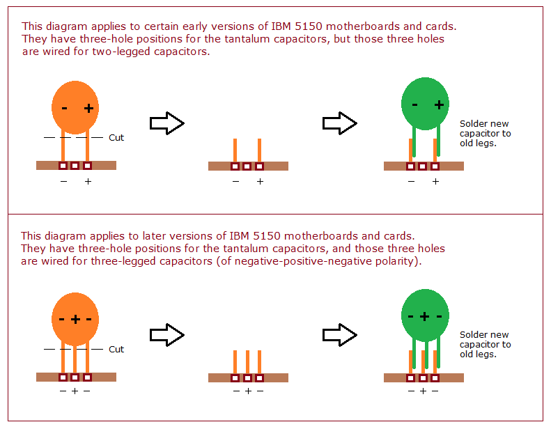
[edit | edit source]Each tantalum position on an IBM 51xx board or card has three holes, wired in one of two ways:[10]
- Wired for 2-legged capacitors, the holes are negative, negative, positive, with a + printed beside the positive hole.
- Wired for 3-legged capacitors, the holes are negative, positive, negative: the centre hole is positive.
In both cases the positive leg goes in the hole marked + on the silkscreen. On a 3-legged position the two outer holes are the negative side: ground on a +5 V or +12 V position, but the supply line itself on a −5 V or −12 V position (C68, C58), where the centre hole is ground.[11] A 2-legged part is fine there with its positive leg in the centre hole; a 3-legged replacement must itself be negative-positive-negative, such as the Kemet T398E106M016AT (Mouser 80-T398E106M16AT) that minuszerodegrees.net names.[10]

Soldering technique: SNCTOL
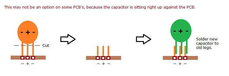
[edit | edit source]minuszerodegrees.net warns that soldering on the 5160 board's ground and power lines is difficult and can damage the board.[5] Its alternative is "solder new capacitor to old legs", which leaves the original pads untouched:[12]
- Cut the old capacitor's legs a few millimetres above the board, leaving the stubs soldered in place.
- Lift the old body away.
- Solder the new capacitor to the stubs, keeping the polarity.
Where the original sits flat against the board there is no leg to graft onto, and the part has to be desoldered in the usual way.[12]

Replacement parts
[edit | edit source]- Dipped tantalum, 10 µF, 16 V or higher; 25 V is acceptable.[7]
- For a 3-legged position: Kemet T398E106M016AT (Mouser 80-T398E106M16AT).[10]
Capacitor replacement procedure
[edit | edit source]- Disconnect the mains lead. Remove the five system cover screws and slide the cover forward.[13] Some drive screws are reached through a well in the underside of the case.[2]
- Disconnect the drive cables and remove all expansion cards, noting their slots. Unplug P8 and P9.
- Photograph the board before desoldering.
- Replace the tantalums one position at a time, using SNCTOL where the old legs allow.
- Fit each new part with its positive leg in the hole marked +.
- Clean off flux with isopropyl alcohol and check for bridges.
- Power up with only the display adapter fitted and check the rails before refitting the rest.
Finding a short-circuit tantalum
[edit | edit source]minuszerodegrees.net's procedure starts from the minimum diagnostic configuration:[14]
- Remove every expansion card and unplug the keyboard and the drive power cables, leaving only the system board and speaker on the supply.
- Switch on. If the fan does not turn, or turns only for a moment, switch off, unplug P8 and switch on again.
- If the fan now runs, the board is loading the supply down.
- With the supply disconnected, measure resistance from +5 V and from +12 V to ground.
- For a +12 V short, remove C56; if the short remains, C55 is the only other component.[5]
- For a +5 V short, look for a marked tantalum among the thirteen; failing that, remove them one at a time until the short clears.[6]
- If the board is clear, refit the cards and drives one at a time, switching off between each, to find the one with the short.
Leave at least one second between switching the supply off and on again, or it may not regenerate power good.[1]
Expansion card capacitors
[edit | edit source]Tantalum failures also occur on IBM adapter cards; the IBM EGA card can report its own faults with one long and three short beeps.[4][15] Cards use the same 10 µF parts and three-hole footprint, wired for two or three legs depending on the card.[10] minuszerodegrees.net publishes no per-card map of positions, so find the card by elimination: if the board runs with no cards but the supply shuts down with one card fitted, that card has the short.
Power supply capacitors
[edit | edit source]The 130 W supply comes in separate 120 V and 220/240 V versions, IBM FRUs 8529247 and 8654269.[1][13] minuszerodegrees.net publishes a procedure for converting a 120 V unit to 240 V.[16]
IBM published no circuit diagram of the supply, and the circuit varied between 110 V and 220 V units and between makers. minuszerodegrees.net links a diagram of one variation from a SAMS Computerfacts document.[3] Read the values off the capacitors in the unit you have, and replace like for like with equal or higher voltage and temperature ratings. Mains X and Y capacitors must be replaced with parts of the same safety class.
Turning off the red switch does not remove mains voltage from everything inside the supply, and the primary capacitors can hold a dangerous charge after the machine is unplugged. Not every unit has a bleeder resistor, so measure the capacitor voltage before touching it.[16][17]
Post-recap voltage checks
[edit | edit source]Measure with the supply connected to the system board and only the display adapter fitted. A working board alone is normally, not always, enough load.[16] IBM's service limits at the board connectors, and the Technical Reference load ranges and sense levels:[18][1]
| Rail | Load, min–max (TR p. 3-4) | Service limits (SIM p. 4-3) | Sense level for power good (TR p. 3-4) |
|---|---|---|---|
| +5 V | 2.3–15.0 A | +4.8 to +5.25 V | +4.5 V |
| −5 V | 0–0.3 A | −4.6 to −5.5 V | −4.3 V |
| +12 V | 0.4–4.2 A | +11.5 to +12.6 V | +10.8 V |
| −12 V | 0–0.25 A | −10.9 to −13.2 V | −10.2 V |
Power good is TTL high when the supply is good and rises between 100 ms and 500 ms after the outputs reach their sense levels.[1] The primary fuses are 5.0 A on 110 V units and 3.5 A on 220/240 V units.[1] The Technical Reference gives no ripple figure for this supply.
A 1701 error after a recap is not a system board error; the fixed disk controller's own ROM produces it.[15]
References
[edit | edit source]- ↑ 1.0 1.1 1.2 1.3 1.4 1.5 1.6 1.7 IBM, Personal Computer XT and Portable Personal Computer Technical Reference, part 6139821, March 1986, hosted as File:IBM PC XT 5155 5160 Technical Reference Mar86.pdf. 64/256K system board logic diagram sheet 10 of 11 (p. 1-44) and the equivalent 256/640K sheet (p. 1-56), showing the power connector and filter capacitors; power supply description, load range, sense levels, fuses and power good (pp. 3-3 to 3-5).
- ↑ 2.0 2.1 2.2 IBM 5160 – Basics, for 5160 beginners, minuszerodegrees.net. Supply shutdown on overload with the fan still turning, the one-second minimum off time, and the advice to wear glasses when first powering equipment that has not been used for years.
- ↑ 3.0 3.1 IBM 5160 – Circuit diagram for the 130 W power supply unit, minuszerodegrees.net: "In the 5160 manuals, IBM did not provide circuit diagrams of the PSU." 110 V and 220 V variations, different circuits from different makers, and one diagram from a SAMS Computerfacts document.
- ↑ 4.0 4.1 4.2 Commonly Failing Electronic Components (in vintage computers), minuszerodegrees.net. Tantalum failure modes, failures at or soon after power-on, and the higher failure rate on boards left unpowered for years.
- ↑ 5.0 5.1 5.2 5.3 5.4 5.5 Short-circuit on the +12 volt line of an IBM 5150/5155/5160 motherboard, minuszerodegrees.net. C55 (ceramic) and C56 (tantalum) are the only components on the 5160's +12 V line; C56 is the known failure, filters only the slot +12 V, and can be removed; the board may occasionally need more load than itself; the C56 photograph.
- ↑ 6.0 6.1 6.2 6.3 Short-circuit on the +5 volt line of an IBM 5150/5155/5160 motherboard, minuszerodegrees.net: "On a 5160 motherboard (of both types), thirteen of the sixteen tantalum capacitors are on the +5 volt line." Over 95 % of the board's components use +5 V; the photograph of the thirteen capacitors.
- ↑ 7.0 7.1 IBM 51xx motherboards/cards – types wired to use 2-legged tantalum capacitors, minuszerodegrees.net. Replacement value 10 µF at 16 V, a higher rating such as 25 V acceptable, and the positive-hole marking.
- ↑ Vintage Computers – Filter Capacitors, minuszerodegrees.net. Which filter capacitors matter, and the 5160's −12 V line feeding only the slots.
- ↑ History of 5150/5155/5160/5170 motherboard failure at the VCF, minuszerodegrees.net.
- ↑ 10.0 10.1 10.2 10.3 Tantalum capacitors on IBM 51xx motherboards/cards, minuszerodegrees.net, with its pages on 2-legged and 3-legged wiring. The three-hole footprint, both wiring variants, the negative-positive-negative order of the 3-legged variant, and the Kemet part.
- ↑ IBM 51xx motherboards/cards that are wired for 3-legged tantalum capacitors (diagram), minuszerodegrees.net: hole wiring for +5 V, +12 V, −5 V and −12 V positions.
- ↑ 12.0 12.1 SNCTOL diagram for the IBM 5160 and the 5150 version, minuszerodegrees.net. "Solder new capacitor to old legs" and the cut-and-graft sequence.
- ↑ 13.0 13.1 IBM, Hardware Maintenance Service parts catalogue, part 6280087 (PC, XT and Portable PC), hosted as File:IBM Hardware Maintenance Service 6280087 Parts Catalog (PC, XT, Portable PC).pdf. 5160 system unit interior, p. 12: cover screws (quantity 5) and supplies 8529247 (120 V) and 8654269 (220/240 V).
- ↑ IBM 5150/5155/5160 – Minimum Diagnostic Configuration, minuszerodegrees.net, and fan not turning.
- ↑ 15.0 15.1 IBM 5160 – POST – Some errors, minuszerodegrees.net.
- ↑ 16.0 16.1 16.2 IBM 5160 – Power Supply Unit, minuszerodegrees.net. Mains still present inside with the switch off, the start-up loading behaviour, and the 120 V to 240 V conversion.
- ↑ IBM 51xx PC Family Computers – Some Hazards Within, minuszerodegrees.net. Mains present with the switch off, the bleeder-resistor caveat, checking discharge with a meter, and beryllium oxide in period thermal paste.
- ↑ IBM, Personal Computer Family Service Information Manual, SA38-0037-00, First Edition, January 1989, chapter 4, p. 4-3, Figure 4-5 "Power Supply Voltages", hosted as File:IBM Personal Computer Family Service Information Manual SA38-0037-00.pdf.
Related pages
[edit | edit source]- IBM PC XT (5160)
- IBM PC XT Maintenance Guide
- IBM PC XT Troubleshooting Guide
- IBM PC (5150) Capacitor Replacement Guide
- Capacitor Failure Symptoms