

Commodore PET 4000 Series: Difference between revisions
No edit summary |
Cite to Commodore drawings 8032090 and 8032051 in the hosted PET 4000 Technical Manual: three on-board regulators (VR4 LM323 +5 V, VR2 7812 +12 V, VR1 7905 -5 V), 16 MHz Y1, full electrolytic list, supply chassis is transformer + 23,000 uF C1 + 1.6 A slow-blow F1 with no regulator; remove red links |
||
| (3 intermediate revisions by the same user not shown) | |||
| Line 2: | Line 2: | ||
| name = Commodore PET 4000 Series | | name = Commodore PET 4000 Series | ||
| image = [[File:Commodore PET 4032 Side.jpg|250px]] | | image = [[File:Commodore PET 4032 Side.jpg|250px]] | ||
| caption = Commodore PET 4032 with 12 | | caption = Commodore PET 4032 with the 12-inch monitor | ||
| manufacturer = Commodore | | manufacturer = Commodore Business Machines | ||
| type = Personal | | type = Personal computer | ||
| release date = 1980 | | release date = 1980 | ||
| discontinued = 1982 | | discontinued = 1982 | ||
| cpu = MOS Technology 6502 @ 1 MHz | | cpu = MOS Technology 6502 @ 1 MHz | ||
| memory = 8 KB | | memory = 8 KB, 16 KB or 32 KB dynamic RAM, by model | ||
| storage = | | storage = IEEE-488 floppy drives; two external cassette ports | ||
| display = 9 | | display = Built-in 9-inch or 12-inch monochrome CRT, 40×25 text | ||
| sound = | | sound = Piezo-acoustic transducer, MT1, driven from the 6522 | ||
| | | power = Internal linear supply: transformer, 23,000 µF filter, 1.6 A slow-blow fuse | ||
| os = Commodore BASIC 4.0 | | os = Commodore BASIC 4.0 | ||
| predecessor = [[Commodore PET 2001]] | | predecessor = [[Commodore PET 2001]] | ||
| successor = | | successor = CBM 8000 series | ||
| model = 4008, 4016, 4032 | | model = 4008, 4016, 4032 | ||
| logo = [[File:Commodore PET logo-03.svg|250px]] | | logo = [[File:Commodore PET logo-03.svg|250px]] | ||
}} | }} | ||
<templatestyles src="Template:StyledTable/styles.css" /> | |||
The '''Commodore PET 4000 Series''' was introduced in 1980, replacing the PET 2001 and 3000 machines. It brought '''Commodore BASIC 4.0''' with its disk commands, and it is built on the '''universal dynamic PET''' board — a completely different design from the static board in the original [[Commodore PET 2001]], with different rails, different regulators and a different crystal. | |||
The | '''The hardware figures on this page are read directly from Commodore's own drawings''' in the ''PET 4000 Series Technical Manual'', P/N 990438, hosted here.<ref name="tm4k">Commodore Business Machines, ''PET 4000 Series Technical Manual'', P/N 990438, for models 4016 and 4032, hosted at [[Commodore PET 4000 Series Technical Manual]]. Drawing '''8032090 Rev H, "PCB ASSY – UNIV. DYNAMIC PET"''': sheet 3 gives the board's capacitors and transistors by reference designator and Commodore part number; sheet 4 gives the diodes, the three voltage regulators (VR1 a 7905 at −5 V/1.5 A, part 901527-03; VR2 a 7812 at +12 V/1 A, part 901528-04; VR4 an LM323 in TO-3, part 901528-01), the 7.5 V zeners VR5 and VR6, the 16 MHz crystal Y1, the socket and header list, the 2.2 µH inductors L1 and L2, and the heatsinks. Drawing '''8032051 Rev E, "Power Supply Assy, 8032"''': the supply chassis consists of transformer T1 (320902-01) on universal power chassis 8032043-02, filter capacitor C1 of '''23,000 µF''' (900102-01), the dynamic PET power harness 320289-01, fuse F1 '''125 V slow-blow 1.6 A''' (903557-04), fuse holder XF1 and rocker switch SW1 — and no voltage regulator and no mains-rated suppression capacitor. Also drawings 321450 and following for the 12-inch and 9-inch CRT displays.</ref> Where the manual does not give a figure, none is given here. | ||
== | == Architecture and processor == | ||
A '''MOS Technology 6502''' at 1 MHz. The master crystal '''Y1 is 16 MHz''' on this board — twice the 8 MHz of the PET 2001, which is the quickest way to tell the two board generations apart on the bench.<ref name="tm4k" /> | |||
Commodore BASIC 4.0 in ROM adds the disk commands (<code>DLOAD</code>, <code>DSAVE</code>, <code>CATALOG</code>, <code>SCRATCH</code> and the rest) that make an IEEE-488 drive usable without wading through the command channel. | |||
== | == Power and rails == | ||
'''The supply chassis contains no regulator.''' Commodore's ''Power Supply Assy, 8032'' drawing lists a transformer, one filter capacitor, a fuse, a fuse holder and a rocker switch — nothing else.<ref name="tm4k" /> | |||
{| class="wikitable styled-table" style="width:95%; text-align:left;" | |||
* | |+'''Supply chassis, Commodore drawing 8032051''' | ||
* CRT display | ! Ref !! Part !! Commodore part no. | ||
|- | |||
| '''T1''' || Transformer, on the universal power chassis 8032043-02 || 320902-01 | |||
|- | |||
| '''C1''' || Filter capacitor, '''23,000 µF''' || 900102-01 | |||
|- | |||
| '''F1''' || Fuse, '''125 V slow-blow, 1.6 A''' || 903557-04 | |||
|- | |||
| XF1, SW1 || Fuse holder and rocker switch || 903611-03, 904507-01 | |||
|- | |||
| — || Dynamic PET power harness || 320289-01 | |||
|} | |||
'''C1 is a 23,000 µF can and it stores real energy.''' Bleed it through a resistor before working near the chassis; do not short it with a screwdriver. Mains is present on the primary side of T1 whenever the machine is plugged in. | |||
All the regulation happens '''on the logic board''':<ref name="tm4k" /> | |||
{| class="wikitable styled-table" style="width:95%; text-align:left;" | |||
|+'''Regulators on the universal dynamic PET board, drawing 8032090''' | |||
! Ref !! Device !! Output !! Commodore part no. | |||
|- | |||
| '''VR1''' || 7905 || '''−5 V''', 1.5 A || 901527-03 | |||
|- | |||
| '''VR2''' || 7812 || '''+12 V''', 1 A || 901528-04 | |||
|- | |||
| '''VR4''' || '''LM323''', TO-3 || +5 V || 901528-01 | |||
|- | |||
| VR5, VR6 || 7.5 V zener diodes || — || 900941-01 | |||
|} | |||
'''The +5 V regulator is an LM323, not a 7805.''' It is the same TO-3 5 A part Commodore used in the early [[Commodore VIC-20]], and it is not a drop-in swap for a 1 A TO-220 device. | |||
'''There is a −5 V rail on this machine.''' That is a real difference from the PET 2001, which has none — so a rail list copied between the two will be wrong in one direction or the other. | |||
Rectification on the board is by bridges CR2 and CR4 (4 A / 50 V) and diodes CR1, CR5 and CR7 (1N4005), with CR3 a 1N5402.<ref name="tm4k" /> | |||
== Storage and I/O == | |||
There is '''no internal cassette deck''' on a 4000-series machine. Storage is: | |||
* '''IEEE-488 (GPIB)''' — Commodore 4040 and 8050 drives, and IEEE printers | |||
* '''Two cassette ports''' — for external Datassettes | |||
* The user port and the memory expansion connector | |||
== Video and sound == | |||
Character-based, 40 columns by 25 rows, on a built-in 9-inch or 12-inch monochrome CRT. The technical manual carries separate drawing sets for the two display sizes, beginning at drawing 321450 for the 12-inch.<ref name="tm4k" /> | |||
Unlike the original PET 2001, the 4000-series board carries a '''piezo-acoustic transducer at MT1''' (Commodore part 907300-02), driven from the 6522's CB2 line — which is where the PET's characteristic beep comes from.<ref name="tm4k" /> | |||
== Electrolytics on the logic board == | |||
Commodore's own list for the universal dynamic PET board. This is the whole electrolytic complement; everything else in the C1–C97 range on that board is a ceramic, a mica or a tantalum.<ref name="tm4k" /> | |||
{| class="wikitable styled-table" style="width:100%; text-align:left;" | |||
{| class="wikitable" style="width: | |+'''Universal dynamic PET board, drawing 8032090 sheet 3''' | ||
! Ref !! Value !! Type !! Commodore part no. | |||
|- | |||
| '''C1, C16, C17, C23, C24''' || 10 µF 25 V || Electrolytic, '''low-leakage''' || 900109-03 | |||
|- | |||
| '''C2''' || 4700 µF 16 V || Electrolytic || 900100-44 | |||
|- | |||
| '''C5''' || 4700 µF 25 V || Electrolytic || 900100-45 | |||
|- | |- | ||
| '''C7, C11''' || 47 µF 16 V || Electrolytic || 900101-37 | |||
|- | |- | ||
| | | C6, C51 || 1 µF 35 V || '''Tantalum''' — fit a tantalum || 900402-13 | ||
| | |||
|} | |} | ||
=== | '''C1, C16, C17, C23 and C24 are specified as low-leakage parts''', not ordinary electrolytics; Commodore calls them out as such in the list. C2 and C5 are the same value at different voltage ratings and are not interchangeable in the safe direction — '''C5 is the 25 V part'''. | ||
No capacitor replacement guide has been written for this machine yet; the list above is what Commodore published. | |||
=== Motherboard === | |||
{| class="wikitable styled-table" style="width:70%; text-align:center;" | |||
|- | |||
! Logic board | |||
|- | |||
| [[File:PET4000 Logic Board.jpg|thumb|center|350px|Commodore PET 4000 Series logic board]] | |||
|} | |||
== Common faults == | |||
* '''Display anomalies.''' The CRT board and its filter capacitors, then the video section of the logic board. | |||
* '''Keyboard.''' Worn contacts and debris in the full-travel switches. | |||
* '''Boot failures.''' ROM or dynamic RAM, or a rail that is out — check all three of +5 V, +12 V and −5 V before condemning a chip. | |||
For fault-finding see [[Commodore PET 4000 Series Troubleshooting Guide]]; for routine care see [[Commodore PET 4000 Series Maintenance Guide]]. | |||
== Documentation hosted here == | |||
* '''[[Commodore PET 4000 Series Technical Manual]]''' — Commodore's drawing set, P/N 990438 | |||
* [[Commodore PET 2001 Service Documentation]] — for the earlier static board | |||
== | == Gallery == | ||
<gallery mode="packed" heights="200"> | <gallery mode="packed" heights="200"> | ||
File:Commodore PET 4032 Side.jpg|Side view of a PET 4032 | |||
File:Commodore PET 4032 Side.jpg|Side view of a PET 4032 | File:Commodore PET 4000 Open.jpg|A PET 4032 with the top lifted | ||
File:Commodore PET | |||
</gallery> | </gallery> | ||
== | == Related pages == | ||
* [[Commodore PET 2001]] | |||
* [[Commodore PET 4000 Series Maintenance Guide]] | * [[Commodore PET 4000 Series Maintenance Guide]] | ||
* [[Commodore PET 4000 Series Troubleshooting Guide]] | * [[Commodore PET 4000 Series Troubleshooting Guide]] | ||
* [[ | * [[CRT Discharge Procedure]] | ||
== References == | |||
<references /> | |||
[[Category:Commodore Systems]] | [[Category:Commodore Systems]] | ||
Latest revision as of 20:05, 23 September 2026
 | |
 | |
| Commodore PET 4032 with the 12-inch monitor | |
| Specifications | |
|---|---|
| Manufacturer | Commodore Business Machines |
| Type | Personal computer |
| Released | 1980 |
| Discontinued | 1982 |
| CPU | MOS Technology 6502 @ 1 MHz |
| Memory | 8 KB, 16 KB or 32 KB dynamic RAM, by model |
| Storage | IEEE-488 floppy drives; two external cassette ports |
| Display | Built-in 9-inch or 12-inch monochrome CRT, 40×25 text |
| Sound | Piezo-acoustic transducer, MT1, driven from the 6522 |
| Power | Internal linear supply: transformer, 23,000 µF filter, 1.6 A slow-blow fuse |
| OS / Firmware | Commodore BASIC 4.0 |
| Predecessor | Commodore PET 2001 |
| Successor | CBM 8000 series |
| Model no. | 4008, 4016, 4032 |
The Commodore PET 4000 Series was introduced in 1980, replacing the PET 2001 and 3000 machines. It brought Commodore BASIC 4.0 with its disk commands, and it is built on the universal dynamic PET board — a completely different design from the static board in the original Commodore PET 2001, with different rails, different regulators and a different crystal.
The hardware figures on this page are read directly from Commodore's own drawings in the PET 4000 Series Technical Manual, P/N 990438, hosted here.[1] Where the manual does not give a figure, none is given here.
Architecture and processor
[edit | edit source]A MOS Technology 6502 at 1 MHz. The master crystal Y1 is 16 MHz on this board — twice the 8 MHz of the PET 2001, which is the quickest way to tell the two board generations apart on the bench.[1]
Commodore BASIC 4.0 in ROM adds the disk commands (DLOAD, DSAVE, CATALOG, SCRATCH and the rest) that make an IEEE-488 drive usable without wading through the command channel.
Power and rails
[edit | edit source]The supply chassis contains no regulator. Commodore's Power Supply Assy, 8032 drawing lists a transformer, one filter capacitor, a fuse, a fuse holder and a rocker switch — nothing else.[1]
| Ref | Part | Commodore part no. |
|---|---|---|
| T1 | Transformer, on the universal power chassis 8032043-02 | 320902-01 |
| C1 | Filter capacitor, 23,000 µF | 900102-01 |
| F1 | Fuse, 125 V slow-blow, 1.6 A | 903557-04 |
| XF1, SW1 | Fuse holder and rocker switch | 903611-03, 904507-01 |
| — | Dynamic PET power harness | 320289-01 |
C1 is a 23,000 µF can and it stores real energy. Bleed it through a resistor before working near the chassis; do not short it with a screwdriver. Mains is present on the primary side of T1 whenever the machine is plugged in.
All the regulation happens on the logic board:[1]
| Ref | Device | Output | Commodore part no. |
|---|---|---|---|
| VR1 | 7905 | −5 V, 1.5 A | 901527-03 |
| VR2 | 7812 | +12 V, 1 A | 901528-04 |
| VR4 | LM323, TO-3 | +5 V | 901528-01 |
| VR5, VR6 | 7.5 V zener diodes | — | 900941-01 |
The +5 V regulator is an LM323, not a 7805. It is the same TO-3 5 A part Commodore used in the early Commodore VIC-20, and it is not a drop-in swap for a 1 A TO-220 device.
There is a −5 V rail on this machine. That is a real difference from the PET 2001, which has none — so a rail list copied between the two will be wrong in one direction or the other.
Rectification on the board is by bridges CR2 and CR4 (4 A / 50 V) and diodes CR1, CR5 and CR7 (1N4005), with CR3 a 1N5402.[1]
Storage and I/O
[edit | edit source]There is no internal cassette deck on a 4000-series machine. Storage is:
- IEEE-488 (GPIB) — Commodore 4040 and 8050 drives, and IEEE printers
- Two cassette ports — for external Datassettes
- The user port and the memory expansion connector
Video and sound
[edit | edit source]Character-based, 40 columns by 25 rows, on a built-in 9-inch or 12-inch monochrome CRT. The technical manual carries separate drawing sets for the two display sizes, beginning at drawing 321450 for the 12-inch.[1]
Unlike the original PET 2001, the 4000-series board carries a piezo-acoustic transducer at MT1 (Commodore part 907300-02), driven from the 6522's CB2 line — which is where the PET's characteristic beep comes from.[1]
Electrolytics on the logic board
[edit | edit source]Commodore's own list for the universal dynamic PET board. This is the whole electrolytic complement; everything else in the C1–C97 range on that board is a ceramic, a mica or a tantalum.[1]
| Ref | Value | Type | Commodore part no. |
|---|---|---|---|
| C1, C16, C17, C23, C24 | 10 µF 25 V | Electrolytic, low-leakage | 900109-03 |
| C2 | 4700 µF 16 V | Electrolytic | 900100-44 |
| C5 | 4700 µF 25 V | Electrolytic | 900100-45 |
| C7, C11 | 47 µF 16 V | Electrolytic | 900101-37 |
| C6, C51 | 1 µF 35 V | Tantalum — fit a tantalum | 900402-13 |
C1, C16, C17, C23 and C24 are specified as low-leakage parts, not ordinary electrolytics; Commodore calls them out as such in the list. C2 and C5 are the same value at different voltage ratings and are not interchangeable in the safe direction — C5 is the 25 V part.
No capacitor replacement guide has been written for this machine yet; the list above is what Commodore published.
Motherboard
[edit | edit source]| Logic board |
|---|
 |
Common faults
[edit | edit source]- Display anomalies. The CRT board and its filter capacitors, then the video section of the logic board.
- Keyboard. Worn contacts and debris in the full-travel switches.
- Boot failures. ROM or dynamic RAM, or a rail that is out — check all three of +5 V, +12 V and −5 V before condemning a chip.
For fault-finding see Commodore PET 4000 Series Troubleshooting Guide; for routine care see Commodore PET 4000 Series Maintenance Guide.
Documentation hosted here
[edit | edit source]- Commodore PET 4000 Series Technical Manual — Commodore's drawing set, P/N 990438
- Commodore PET 2001 Service Documentation — for the earlier static board
Gallery
[edit | edit source]-
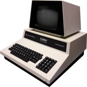 Side view of a PET 4032
 -
 A PET 4032 with the top lifted

Related pages
[edit | edit source]- Commodore PET 2001
- Commodore PET 4000 Series Maintenance Guide
- Commodore PET 4000 Series Troubleshooting Guide
- CRT Discharge Procedure
References
[edit | edit source]- ↑ 1.0 1.1 1.2 1.3 1.4 1.5 1.6 1.7 Commodore Business Machines, PET 4000 Series Technical Manual, P/N 990438, for models 4016 and 4032, hosted at Commodore PET 4000 Series Technical Manual. Drawing 8032090 Rev H, "PCB ASSY – UNIV. DYNAMIC PET": sheet 3 gives the board's capacitors and transistors by reference designator and Commodore part number; sheet 4 gives the diodes, the three voltage regulators (VR1 a 7905 at −5 V/1.5 A, part 901527-03; VR2 a 7812 at +12 V/1 A, part 901528-04; VR4 an LM323 in TO-3, part 901528-01), the 7.5 V zeners VR5 and VR6, the 16 MHz crystal Y1, the socket and header list, the 2.2 µH inductors L1 and L2, and the heatsinks. Drawing 8032051 Rev E, "Power Supply Assy, 8032": the supply chassis consists of transformer T1 (320902-01) on universal power chassis 8032043-02, filter capacitor C1 of 23,000 µF (900102-01), the dynamic PET power harness 320289-01, fuse F1 125 V slow-blow 1.6 A (903557-04), fuse holder XF1 and rocker switch SW1 — and no voltage regulator and no mains-rated suppression capacitor. Also drawings 321450 and following for the 12-inch and 9-inch CRT displays.