

Macintosh Classic II Capacitor Replacement Guide: Difference between revisions
No edit summary |
No edit summary |
||
| Line 1: | Line 1: | ||
'''Replacing electrolytic capacitors (recapping) in your Macintosh Classic II''' is essential for restoring power stability, ensuring clean video output, and preventing long‑term damage due to leakage. This guide outlines the recommended procedure and provides complete analog and logic board capacitor specifications. | '''Replacing electrolytic capacitors (recapping) in your Macintosh Classic II''' is essential for restoring power stability, ensuring clean video output, and preventing long‑term damage due to leakage. This guide outlines the recommended procedure and provides complete analog and logic board capacitor specifications. | ||
== | == Capacitor Inspection == | ||
Before recapping, visually inspect all capacitors for common signs of failure: | Before recapping, visually inspect all capacitors for common signs of failure: | ||
* '''Bulging Tops''' – Swollen or domed caps indicate internal gas buildup. | * '''Bulging Tops''' – Swollen or domed caps indicate internal gas buildup. | ||
| Line 9: | Line 9: | ||
If any symptoms are present, immediate replacement is advised. | If any symptoms are present, immediate replacement is advised. | ||
== | == Macintosh Classic II Capacitor List == | ||
=== | === Analog Board Capacitors === | ||
The Classic II shares its analog board with the Classic. Due to board revisions, labels may vary—always verify against your schematic. | The Classic II shares its analog board with the Classic. Due to board revisions, labels may vary—always verify against your schematic. | ||
| Line 71: | Line 71: | ||
|} | |} | ||
''Note: Values may vary between revisions—always cross-check your board.'' | |||
[[File:Mac_classic_analog_recap.jpg|thumb|694x694px|Macintosh Classic II Analog Board Recap Diagram|center]] | [[File:Mac_classic_analog_recap.jpg|thumb|694x694px|Macintosh Classic II Analog Board Recap Diagram|center]] | ||
=== | === Logic Board Capacitors === | ||
Two logic board revisions exist—Rev A has 13 caps, Rev B has 17. | Two logic board revisions exist—Rev A has 13 caps, Rev B has 17. | ||
| Line 97: | Line 97: | ||
|} | |} | ||
''Tip: If substituting tantalum, choose 25 V ratings for the 47 µF positions.'' | |||
<gallery mode="packed" heights="250"> | <gallery mode="packed" heights="250"> | ||
File:Classic II (A) recapping.jpg|Macintosh Classic II (Rev A) Logic Board Recap Diagram | File:Classic II (A) recapping.jpg|Macintosh Classic II (Rev A) Logic Board Recap Diagram | ||
| Line 103: | Line 103: | ||
</gallery> | </gallery> | ||
== | == Capacitor Replacement Procedure == | ||
# '''Discharge the CRT''' – Follow standard CRT discharge steps before opening the case. | # '''Discharge the CRT''' – Follow standard CRT discharge steps before opening the case. | ||
# '''Remove the Boards''' – Label connectors; carefully extract the logic and analog boards. | # '''Remove the Boards''' – Label connectors; carefully extract the logic and analog boards. | ||
| Line 113: | Line 113: | ||
# '''Test for Shorts''' – Verify with a multimeter across each power rail. | # '''Test for Shorts''' – Verify with a multimeter across each power rail. | ||
== | == Recommended Tools == | ||
* Temperature‑controlled soldering iron (fine tip) | * Temperature‑controlled soldering iron (fine tip) | ||
* Desoldering braid or vacuum pump | * Desoldering braid or vacuum pump | ||
| Line 121: | Line 121: | ||
* Safety goggles & insulated gloves | * Safety goggles & insulated gloves | ||
== | == Voltage Adjustment After Recap == | ||
With boards reinstalled, measure at the floppy‑drive power pins: | With boards reinstalled, measure at the floppy‑drive power pins: | ||
* '''+5 V rail:''' 4.90 – 5.15 V | * '''+5 V rail:''' 4.90 – 5.15 V | ||
| Line 127: | Line 127: | ||
Use the analog board’s variable resistor (PP1) to fine‑tune. | Use the analog board’s variable resistor (PP1) to fine‑tune. | ||
== | == Tips for Best Results == | ||
* Recap the logic board first—its leakage often damages the analog side. | * Recap the logic board first—its leakage often damages the analog side. | ||
* Use top‑tier caps (Nichicon, Panasonic, Rubycon). | * Use top‑tier caps (Nichicon, Panasonic, Rubycon). | ||
| Line 134: | Line 134: | ||
* Always clean the board thoroughly post‑recap. | * Always clean the board thoroughly post‑recap. | ||
== | == Related Pages == | ||
* [[Macintosh Classic / Classic II General Maintenance]] | * [[Macintosh Classic / Classic II General Maintenance]] | ||
* [[Macintosh Classic / Classic II Troubleshooting]] | * [[Macintosh Classic / Classic II Troubleshooting]] | ||
| Line 143: | Line 143: | ||
[[Category:Apple Vintage Computers]] | [[Category:Apple Vintage Computers]] | ||
[[Category:Capacitor Replacement Guides]] | [[Category:Capacitor Replacement Guides]] | ||
Revision as of 09:06, 12 May 2025
Replacing electrolytic capacitors (recapping) in your Macintosh Classic II is essential for restoring power stability, ensuring clean video output, and preventing long‑term damage due to leakage. This guide outlines the recommended procedure and provides complete analog and logic board capacitor specifications.
Capacitor Inspection
Before recapping, visually inspect all capacitors for common signs of failure:
- Bulging Tops – Swollen or domed caps indicate internal gas buildup.
- Electrolyte Leakage – Brown/white crust or residue near leads shows failure.
- Corroded Pads or Traces – PCB staining or corrosion suggests damage.
If any symptoms are present, immediate replacement is advised.
Macintosh Classic II Capacitor List
Analog Board Capacitors
The Classic II shares its analog board with the Classic. Due to board revisions, labels may vary—always verify against your schematic.
| Label | Capacitance | Voltage | Qty |
|---|---|---|---|
| CF3 | 1000 µF | 16 V | 1 |
| CF4 | 470 µF | 25 V | 1 |
| CL1 | 1000 µF | 25 V | 1 |
| CL2 | 4.7 µF | 250 V | 1 |
| CL3 | 1 µF | 50 V | 1 |
| CP1 | 220 µF | 250 V | 1 |
| CP10 | 470 µF | 25 V | 1 |
| CP11 | 220 µF | 50 V | 1 |
| CP12 | 1000 µF | 16 V | 1 |
| CP13 | 220 µF | 250 V | 1 |
| CP2 | 470 µF | 50 V | 1 |
| CP34 | 1 µF | 50 V | 1 |
| CP36 | 2200 µF | 10 V | 1 |
| CP4 | 47 µF | 25 V | 1 |
| CP5 | 1 µF | 50 V | 1 |
| CP6 | 2200 µF | 10 V | 1 |
| CP7 | 1000 µF | 10 V | 1 |
| CP8 | 2200 µF | 16 V | 1 |
| CP9 | 470 µF | 25 V | 1 |
| CV2 | 470 µF | 10 V | 1 |
| CP3 | 10 µF | 25 V | 1 |
| CP37 | 1 µF | 50 V | 1 |
| CL11 | 47 µF | 16 V | 1 |
| CF2 | 220 µF | 16 V | 1 |
| CF1 | 47 µF | 25 V | 1 |
Note: Values may vary between revisions—always cross-check your board.

Logic Board Capacitors
Two logic board revisions exist—Rev A has 13 caps, Rev B has 17.
| Revision | Value | Voltage | Qty |
|---|---|---|---|
| Rev A | 47 µF | 16 V | 3 |
| 10 µF | 16 V | 8 | |
| 1 µF | 50 V | 2 | |
| Rev B | 47 µF | 16 V | 3 |
| 10 µF | 16 V | 12 | |
| 1 µF | 50 V | 2 |
Tip: If substituting tantalum, choose 25 V ratings for the 47 µF positions.
-
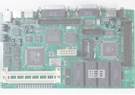 Macintosh Classic II (Rev A) Logic Board Recap Diagram
 -
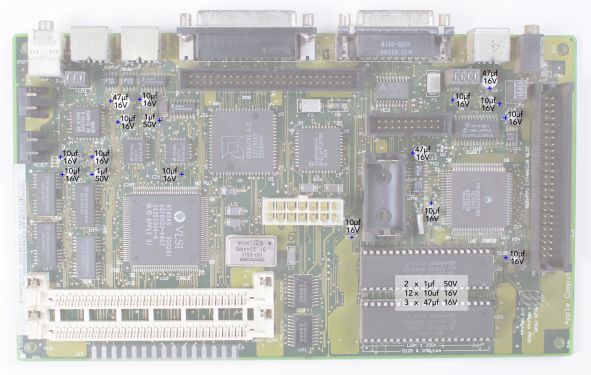 Macintosh Classic II (Rev B) Logic Board Recap Diagram
_recapping.jpg)
_Recapping.jpg)
Capacitor Replacement Procedure
- Discharge the CRT – Follow standard CRT discharge steps before opening the case.
- Remove the Boards – Label connectors; carefully extract the logic and analog boards.
- Desolder Old Caps – Use a temperature‑controlled iron with braid or pump for clean removal.
- Clean the PCB – Remove all electrolyte residue with 99 % IPA and an ESD‑safe brush.
- Install New Caps – Observe polarity (negative stripe); seat flush to the board.
- Solder Carefully – Aim for shiny, sloped joints; avoid cold bridges.
- Trim Leads & Inspect – Cut excess lead length and check with magnification.
- Test for Shorts – Verify with a multimeter across each power rail.
Recommended Tools
- Temperature‑controlled soldering iron (fine tip)
- Desoldering braid or vacuum pump
- Leaded solder, ~0.5 mm diameter
- 99 % isopropyl alcohol & ESD‑safe brush
- Multimeter
- Safety goggles & insulated gloves
Voltage Adjustment After Recap
With boards reinstalled, measure at the floppy‑drive power pins:
- +5 V rail: 4.90 – 5.15 V
- +12 V rail: 11.9 – 12.7 V
Use the analog board’s variable resistor (PP1) to fine‑tune.
Tips for Best Results
- Recap the logic board first—its leakage often damages the analog side.
- Use top‑tier caps (Nichicon, Panasonic, Rubycon).
- Power on the machine periodically after recap to “exercise” new caps.
- Replace complete sets for uniform aging and reliability.
- Always clean the board thoroughly post‑recap.
Related Pages
- Macintosh Classic / Classic II General Maintenance
- Macintosh Classic / Classic II Troubleshooting
- Macintosh Floppy Drive Maintenance
- CRT Discharge Procedure