

File:Video-1.gif


Summary
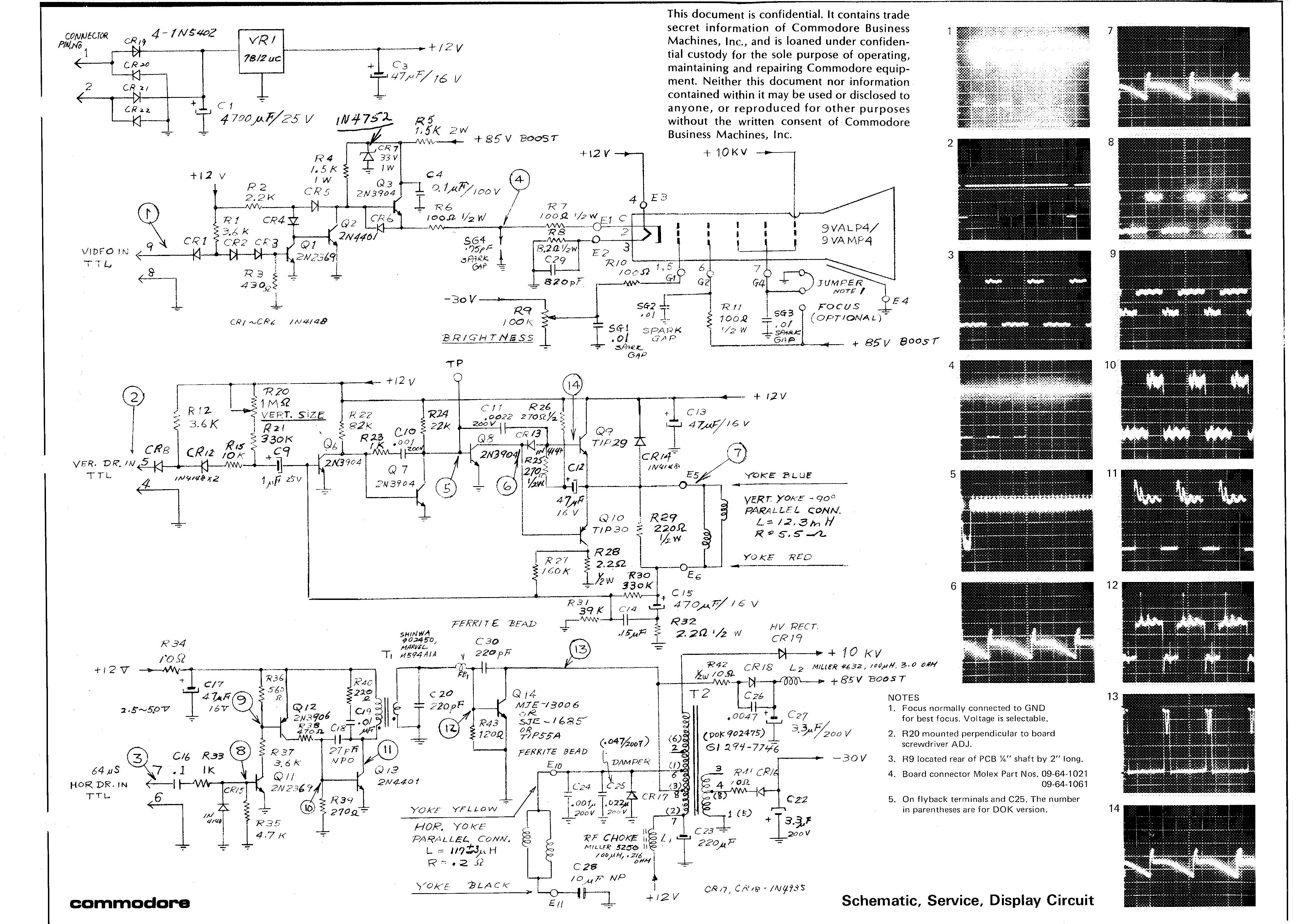
Commodore Business Machines, Inc., Schematic, Service, Display Circuit for the Commodore PET 2001, scanned at 400 dpi. The full component-level circuit of the display assembly — T1, the CR19–CR22 bridge, reservoir C1, regulator VR1 (+12 V), the −30 V and +85 V rails, the horizontal output stage around Q14, flyback T2 (GI 294-7746) and the ~+10 kV anode supply — with fourteen waveform photographs. The oscilloscope settings for those photographs are on a separate sheet, File:notes-2.gif.

Used on
- Video Board Schematic — the documentation page for this file
File
372 KB, image/gif.
Licence
Not freely licensed. Manufacturer service or product documentation remains the manufacturer's copyright. It is hosted here for reference and preservation because the equipment it covers is long out of support. No licence to redistribute is claimed or implied; if the rights holder objects, the file will be removed.
File history
Click on a date/time to view the file as it appeared at that time.
| Date/Time | Thumbnail | Dimensions | User | Comment | |
|---|---|---|---|---|---|
| current | 15:37, 17 April 2025 | | 4,648 × 3,296 (363 KB) | Josh (talk | contribs) | File uploaded with MsUpload Category:Commodore_PET_2001_Schematics |
You cannot overwrite this file.
File usage
The following page uses this file:
