IBM PC (5150) Capacitor Replacement Guide: Difference between revisions
Rewrite with verified information only — remove fabricated part numbers (CGA 1501486, MDA 1501481, FDD Adapter 1501507, Fixed Disk Adapter 6181682, Model F dimensions/weight), remove placeholder image filenames, replace speculative capacitor designator table with verified minuszerodegrees.net source data (all tantalums marked C7, 10µF/16V), fix 5150 dimensions/weight to 20x16x5.5 inches / 21-28 lbs, fix Model F dimensions/weight to 19x9x1.5in / 7lb4oz / 3.3kg. Per Joshua's feedback: never pub... |
Self-sufficient rewrite: embed the actual minuszerodegrees board photos with attribution; embed full IBM PC POST numeric error code tables (1xx through 17xx) inline; embed the known-problems list inline. References now attribute the source rather than substitute for the content. |
||
| Line 1: | Line 1: | ||
<templatestyles src="Template:StyledTable/styles.css" /> | <templatestyles src="Template:StyledTable/styles.css" /> | ||
The '''IBM 5150''' motherboard carries through-hole tantalum capacitors that fail short-circuit and latch the PSU off, producing what looks like a dead motherboard. Recapping the motherboard and PSU is the single most useful preventative job on a 40-plus-year-old 5150. This guide documents | The '''IBM 5150''' motherboard carries through-hole tantalum capacitors that fail short-circuit and latch the PSU off, producing what looks like a dead motherboard. Recapping the motherboard and the PSU is the single most useful preventative job on a 40-plus-year-old 5150. This guide documents the verified per-revision capacitor positions, the failure modes, the soldering technique, and the replacement parts. All board photos and the soldering diagram on this page were imported with attribution from [https://minuszerodegrees.net minuszerodegrees.net], whose long-running 51xx motherboard failure-history work is the primary source for IBM 5150 motherboard capacitor information. | ||
== Visual Inspection & Failure Signs == | == Visual Inspection & Failure Signs == | ||
Before doing any soldering work, examine each board under good light | Before doing any soldering work, examine each board under good light. | ||
[[File:IBM 5150 failed tantalum visual example.jpg|right|thumb|300px|A failed tantalum capacitor on an IBM 51xx motherboard. The small black hole on the body is the only visual indication of failure — in most cases there is no visual sign at all. (Image: minuszerodegrees.net)]] | |||
A failed tantalum may show: | |||
* '''Cracked or discoloured body''' — small yellow or orange dipped bead with a fracture, scorch mark, or darkening. | |||
* '''Small black "eye" or hole''' on the body, as shown in the photo opposite. Often the only visual indication. | |||
* '''Burnt resistor next to the capacitor''' — a tantalum that shorted may have taken out the series resistor on its rail. | |||
* '''Brown halo around the pad''' — conductive residue from a long-failed capacitor. | |||
* '''Sharp electrolyte / burnt smell.''' | |||
In a substantial fraction of cases, a short-circuit tantalum shows '''no''' visual indication at all. Diagnostic methodology (rather than visual inspection) is required. | |||
== IBM 5150 Motherboard Tantalum Capacitors == | |||
All tantalum capacitors on the 5150 motherboard are '''10 µF / 16 V''', and IBM designated many of the positions with the shared silkscreen designator '''C7''' — multiple physical capacitors share the C7 designator on the same board. The exact count differs between the two motherboard revisions. | |||
<templatestyles src="Template:StyledTable/styles.css" /> | |||
{| class="wikitable styled-table" style="width:100%; text-align:center;" | {| class="wikitable styled-table" style="width:100%; text-align:center;" | ||
|+'''IBM 5150 motherboard tantalum | |+'''IBM 5150 motherboard tantalum capacitor inventory''' | ||
! Motherboard revision !! Total tantalums on | ! Motherboard revision !! Total tantalums on board !! On +5 V line !! On +12 V line !! Tantalum value | ||
|- | |- | ||
| 16KB-64KB (early) || 17 || 6 (all marked C7) || 5 (all marked C7 | | 16KB-64KB (early) || 17 || 6 (all marked C7) || 5 (all marked C7) || 10 µF / 16 V | ||
|- | |- | ||
| 64KB-256KB (later) || 13 || 10 (all marked C7) || 1 (filter for expansion | | 64KB-256KB (later) || 13 || 10 (all marked C7) || 1 (filter for expansion slots only) || 10 µF / 16 V | ||
|} | |} | ||
The motherboard also has '''23 ceramic''' decoupling capacitors of value '''0.047 µF''' (marked C3, "K5M"-coded yellow ceramic). Ceramic capacitors | The motherboard also has '''23 ceramic''' decoupling capacitors of value '''0.047 µF''' (marked C3 on the silkscreen, "K5M"-coded yellow ceramic). Ceramic capacitors rarely fail; they do not need preventative replacement. | ||
=== +5 V tantalum capacitors — 16KB-64KB motherboard === | |||
On the early-revision motherboard, six tantalum capacitors sit on the +5 V line. They are highlighted in the photo below. | |||
[[File:IBM 5150 16KB-64KB motherboard +5V tantalums.jpg|center|thumb|720px|IBM 5150 16KB-64KB motherboard. The six tantalum capacitors on the +5 V line (all designated C7, 10 µF / 16 V) are highlighted. (Image: minuszerodegrees.net)]] | |||
If a short-circuit is present on the +5 V rail of the motherboard (PSU latches off the moment the rail comes up), the cause is usually one of these six tantalums. Remove them one at a time (desolder, or snip the leads at the body) until the short clears. Replace all six with new 10 µF / 16 V tantalum (or solid polymer) parts. | |||
== | === +5 V tantalum capacitors — 64KB-256KB motherboard === | ||
On the later-revision motherboard, ten tantalum capacitors sit on the +5 V line. | |||
[[File:IBM 5150 64KB-256KB motherboard +5V tantalums.jpg|center|thumb|720px|IBM 5150 64KB-256KB motherboard. The ten tantalum capacitors on the +5 V line (all designated C7, 10 µF / 16 V) are highlighted. (Image: minuszerodegrees.net)]] | |||
Same diagnostic and replacement approach as the early board. | |||
=== +12 V tantalum capacitors — 16KB-64KB motherboard === | |||
On the early-revision motherboard, five tantalum capacitors sit on the +12 V line, four of which are grouped together near the on-board RAM and are critical to RAM operation. | |||
[[File:IBM 5150 16KB-64KB motherboard +12V tantalums.jpg|center|thumb|720px|IBM 5150 16KB-64KB motherboard. The five tantalum capacitors on the +12 V line are highlighted. The four grouped together are important for on-board RAM operation. (Image: minuszerodegrees.net)]] | |||
Replace all five with new 10 µF / 16 V parts. | |||
=== +12 V tantalum capacitor — 64KB-256KB motherboard === | |||
On the later-revision motherboard, there is '''only one''' component on the +12 V line — a single tantalum capacitor that filters the +12 V going to the expansion slots. It is '''not critical''' to motherboard operation; the board will run without it. | |||
[[File:IBM 5150 64KB-256KB motherboard +12V tantalum.jpg|center|thumb|600px|IBM 5150 64KB-256KB motherboard. The single +12 V tantalum capacitor is highlighted. It filters only the +12 V to the expansion slots and is not critical to motherboard operation. (Image: minuszerodegrees.net)]] | |||
If a +12 V short is present, this is almost certainly the cause. Remove and replace with a new 10 µF / 16 V tantalum; the board can also be operated indefinitely with the capacitor simply removed. | |||
== Polarity == | |||
Tantalum capacitor polarity must be correct or the replacement part will fail explosively the moment power is applied. The positive lead is the longer of the two new-part leads and is marked '''+''' on the body. The PCB pad with the silkscreened '''+''' takes the positive lead. | |||
[[File:IBM 5150 tantalum polarity reference.jpg|center|thumb|720px|Polarity reference for IBM 5150 motherboard tantalum capacitors. (Image: minuszerodegrees.net)]] | |||
== Soldering Technique on the 5150 Motherboard == | |||
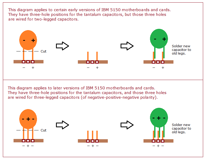
The 5150 motherboard has heavy copper ground and power pours that act as enormous heatsinks. Conventional soldering iron work with an under-powered iron risks lifting the pad. minuszerodegrees.net documents a '''SNCTOL''' technique (Snip, Cut, Tin, Overlap, Solder) that avoids working the pad and is significantly safer for the PCB. | |||
[[File:IBM 5150 SNCTOL soldering technique.png|center|thumb|600px|SNCTOL soldering technique for the IBM 5150 motherboard. (Diagram: minuszerodegrees.net)]] | |||
If using a soldering iron directly, set it to at least '''380 °C''' and use plenty of flux. A hot-air rework station, where available, makes the job substantially easier. | |||
== Replacement Parts == | |||
Use one of: | |||
* '''Modern wet-electrolyte tantalum:''' 10 µF / 16 V dipped tantalum bead (e.g. KEMET T350E106K016AT, AVX TAP106K016). | |||
* '''Solid polymer tantalum:''' 10 µF / 16 V or higher (e.g. KEMET T491A106K016AT). Solid polymer types do not fail short-circuit and are the recommended replacement. | |||
* '''Pre-packaged kit:''' [https://console5.com/store/computer-cap-kits/ibm.html Console5 IBM cap kits]. | |||
Voltage rating of 16 V is the minimum; 25 V or 35 V parts are also acceptable and give greater margin. Do not under-rate. | |||
== Capacitor Replacement Procedure == | == Capacitor Replacement Procedure == | ||
| Line 54: | Line 95: | ||
# '''Disassemble.''' Disconnect mains, remove the five rear cover screws, slide the cover off. Unplug P8/P9 from the motherboard. Remove all ISA cards and the floppy/HDD ribbon cables, labelling each. Remove the four PSU mounting screws and lift the PSU out. | # '''Disassemble.''' Disconnect mains, remove the five rear cover screws, slide the cover off. Unplug P8/P9 from the motherboard. Remove all ISA cards and the floppy/HDD ribbon cables, labelling each. Remove the four PSU mounting screws and lift the PSU out. | ||
# '''Bleed the PSU bulk capacitors.''' The primary-side bulk capacitors retain a dangerous charge for hours after disconnection. Discharge each through a 10 kΩ resistor across the leads for at least 30 seconds, then verify with a multimeter. | # '''Bleed the PSU bulk capacitors.''' The primary-side bulk capacitors retain a dangerous charge for hours after disconnection. Discharge each through a 10 kΩ resistor across the leads for at least 30 seconds, then verify with a multimeter. | ||
# '''Document''' the original capacitor layout with photographs. | # '''Document''' the original capacitor layout with photographs before desoldering anything. | ||
# '''Desolder''' tantalums one at a time. Snip the leads close to the body and lift the body off, then desolder the remaining leads from the pad side. This avoids stressing the pads. | # '''Desolder''' tantalums one at a time. Snip the leads close to the body and lift the body off, then desolder the remaining leads from the pad side. This avoids stressing the pads. Apply the SNCTOL technique on heavy ground/power positions. | ||
# '''Install replacements''' with correct polarity. | # '''Install replacements''' with correct polarity (long lead = +, silkscreen + on the pad). | ||
# '''Clean up''' flux residue with isopropyl alcohol; inspect for solder bridges. | # '''Clean up''' flux residue with isopropyl alcohol; inspect for solder bridges. | ||
# '''Reassemble''', power on with no ISA cards beyond the video adapter, and confirm PSU rails before fitting other cards. | # '''Reassemble''', power on with no ISA cards beyond the video adapter, and confirm PSU rails before fitting other cards. | ||
== Diagnostic Procedure for a Suspected Short-Circuit Tantalum == | |||
If the PSU latches off (the fan may still spin while the rails go to zero) and you suspect a short-circuit motherboard tantalum: | |||
# Disconnect the keyboard. | |||
# Remove every ISA card from the motherboard. | |||
# Try the PSU again with just the motherboard connected. | |||
## If the rails come up cleanly, the short was on one of the removed cards. Re-add cards one at a time, powering down between each. | |||
## If the rails still latch off, the short is on the motherboard. | |||
# With the motherboard isolated, measure the resistance between the +5 V rail and ground, and between the +12 V rail and ground (with the PSU disconnected). A dead short (sub-ohm) indicates a failed tantalum on that rail. | |||
# Find the failed tantalum: | |||
#* '''+5 V short on a 16KB-64KB board:''' one of the six C7 tantalums highlighted in the +5 V photo above. | |||
#* '''+5 V short on a 64KB-256KB board:''' one of the ten C7 tantalums highlighted in the +5 V photo above. | |||
#* '''+12 V short on a 16KB-64KB board:''' one of the five C7 tantalums highlighted in the +12 V photo above. | |||
#* '''+12 V short on a 64KB-256KB board:''' the single tantalum highlighted in the +12 V photo above. | |||
# Remove the suspect capacitor (snip the leads at the body). Re-check the resistance to ground. If the short is gone, the removed capacitor was the failure. If the short remains, restore that capacitor's lead pads and move on to the next position. | |||
== ISA Card Capacitors == | == ISA Card Capacitors == | ||
| Line 69: | Line 127: | ||
* '''[[IBM Fixed Disk Adapter]]''' — tantalum + electrolytic mix near the BIOS expansion ROM. | * '''[[IBM Fixed Disk Adapter]]''' — tantalum + electrolytic mix near the BIOS expansion ROM. | ||
If a card causes the PSU to latch off when plugged in, but the motherboard alone runs cleanly, suspect a short-circuit tantalum on that card. | If a card causes the PSU to latch off when plugged in, but the motherboard alone runs cleanly, suspect a short-circuit tantalum on that card. The same SNCTOL replacement technique applies. | ||
== PSU Capacitor Replacement == | == PSU Capacitor Replacement == | ||
The IBM 5150 PSU (Type 1, 63.5 W; Type 2, 130 W) uses standard wet-electrolytic capacitors on the secondary side and X/Y safety-rated capacitors on the primary side. Both types of PSU benefit from a full recap, with particular attention to: | The IBM 5150 PSU (Type 1, 63.5 W; Type 2, 130 W) uses standard wet-electrolytic capacitors on the secondary side and X/Y safety-rated film capacitors on the primary side. Both types of PSU benefit from a full recap, with particular attention to: | ||
* '''Primary-side bulk filtering''' — high-voltage electrolytics on the rectified-mains side. | * '''Primary-side bulk filtering''' — high-voltage electrolytics on the rectified-mains side. | ||
* '''Output filters''' for +5 V, +12 V, −5 V, −12 V. | * '''Output filters''' for +5 V, +12 V, −5 V, −12 V on the secondary side. | ||
* '''X / Y safety capacitors''' on the mains input — must be replaced with safety-rated parts (X2 / Y1 / Y2 as appropriate), never with generic film capacitors. | * '''X / Y safety capacitors''' on the mains input — must be replaced with safety-rated parts (X2 / Y1 / Y2 as appropriate), never with generic film capacitors. A failed X capacitor is a fire risk. | ||
Specific values vary between PSU manufacturers (Astec, Zenith, IBM-branded variants). Consult the markings on the existing capacitors before ordering replacements; a third-party PSU recap kit such as Console5's covers the standard 5150 PSU. | Specific values vary between PSU manufacturers (Astec, Zenith, IBM-branded variants). Consult the markings on the existing capacitors before ordering replacements; a third-party PSU recap kit such as Console5's covers the standard 5150 PSU. | ||
The three '''BUV46 | The three '''BUV46''' switching transistors in the PSU are a known failure point. If any one tests faulty, replace as a matched set. | ||
== Post-Recap Voltage Checks == | == Post-Recap Voltage Checks == | ||
| Line 89: | Line 147: | ||
== References == | == References == | ||
* [https://www.minuszerodegrees.net/5150_5160/MDC/tantalum_short_plus_5volts.htm Tantalum capacitor short-circuit on the +5 V line], minuszerodegrees.net. | * [https://www.minuszerodegrees.net/5150_5160/MDC/tantalum_short_plus_5volts.htm Tantalum capacitor short-circuit on the +5 V line], minuszerodegrees.net (Brad Parker). Primary source for the per-revision +5 V capacitor positions and the highlighted board photos reproduced above. | ||
* [https://minuszerodegrees.net/5150_5160/MDC/tantalum_short_plus_12volts.htm Tantalum capacitor short-circuit on the +12 V line], minuszerodegrees.net. | * [https://minuszerodegrees.net/5150_5160/MDC/tantalum_short_plus_12volts.htm Tantalum capacitor short-circuit on the +12 V line], minuszerodegrees.net. Primary source for the +12 V capacitor positions reproduced above. | ||
* [https://minuszerodegrees.net/failure/IBM%2051xx%20motherboards%20-%20tantalum%20capacitors.htm IBM 51xx tantalum capacitor replacement details], minuszerodegrees.net. | * [https://minuszerodegrees.net/failure/IBM%2051xx%20motherboards%20-%20tantalum%20capacitors.htm IBM 51xx motherboards — tantalum capacitor replacement details], minuszerodegrees.net. Polarity reference photo source. | ||
* IBM, ''IBM 5150 Technical Reference'' (6025005, August 1981) — schematics. | * [https://www.minuszerodegrees.net/soldering/snctol_5150.png SNCTOL soldering diagram for the 5150 motherboard], minuszerodegrees.net. | ||
* [https://console5.com/store/computer-cap-kits/ibm.html Console5 IBM cap kits]. | * [https://minuszerodegrees.net/failure.htm Failed component visual examples], minuszerodegrees.net. | ||
* IBM, ''IBM 5150 Technical Reference'' (part 6025005, August 1981) — schematics. [https://www.minuszerodegrees.net/manuals/IBM_5150_Technical_Reference_6025005_AUG81.pdf PDF on minuszerodegrees mirror]. | |||
* [https://console5.com/store/computer-cap-kits/ibm.html Console5 — IBM cap kits]. | |||
== Related Pages == | == Related Pages == | ||
Latest revision as of 10:36, 21 May 2026
The IBM 5150 motherboard carries through-hole tantalum capacitors that fail short-circuit and latch the PSU off, producing what looks like a dead motherboard. Recapping the motherboard and the PSU is the single most useful preventative job on a 40-plus-year-old 5150. This guide documents the verified per-revision capacitor positions, the failure modes, the soldering technique, and the replacement parts. All board photos and the soldering diagram on this page were imported with attribution from minuszerodegrees.net, whose long-running 51xx motherboard failure-history work is the primary source for IBM 5150 motherboard capacitor information.
Visual Inspection & Failure Signs
[edit | edit source]Before doing any soldering work, examine each board under good light.

A failed tantalum may show:
- Cracked or discoloured body — small yellow or orange dipped bead with a fracture, scorch mark, or darkening.
- Small black "eye" or hole on the body, as shown in the photo opposite. Often the only visual indication.
- Burnt resistor next to the capacitor — a tantalum that shorted may have taken out the series resistor on its rail.
- Brown halo around the pad — conductive residue from a long-failed capacitor.
- Sharp electrolyte / burnt smell.
In a substantial fraction of cases, a short-circuit tantalum shows no visual indication at all. Diagnostic methodology (rather than visual inspection) is required.
IBM 5150 Motherboard Tantalum Capacitors
[edit | edit source]All tantalum capacitors on the 5150 motherboard are 10 µF / 16 V, and IBM designated many of the positions with the shared silkscreen designator C7 — multiple physical capacitors share the C7 designator on the same board. The exact count differs between the two motherboard revisions.
| Motherboard revision | Total tantalums on board | On +5 V line | On +12 V line | Tantalum value |
|---|---|---|---|---|
| 16KB-64KB (early) | 17 | 6 (all marked C7) | 5 (all marked C7) | 10 µF / 16 V |
| 64KB-256KB (later) | 13 | 10 (all marked C7) | 1 (filter for expansion slots only) | 10 µF / 16 V |
The motherboard also has 23 ceramic decoupling capacitors of value 0.047 µF (marked C3 on the silkscreen, "K5M"-coded yellow ceramic). Ceramic capacitors rarely fail; they do not need preventative replacement.
+5 V tantalum capacitors — 16KB-64KB motherboard
[edit | edit source]On the early-revision motherboard, six tantalum capacitors sit on the +5 V line. They are highlighted in the photo below.

If a short-circuit is present on the +5 V rail of the motherboard (PSU latches off the moment the rail comes up), the cause is usually one of these six tantalums. Remove them one at a time (desolder, or snip the leads at the body) until the short clears. Replace all six with new 10 µF / 16 V tantalum (or solid polymer) parts.
+5 V tantalum capacitors — 64KB-256KB motherboard
[edit | edit source]On the later-revision motherboard, ten tantalum capacitors sit on the +5 V line.

Same diagnostic and replacement approach as the early board.
+12 V tantalum capacitors — 16KB-64KB motherboard
[edit | edit source]On the early-revision motherboard, five tantalum capacitors sit on the +12 V line, four of which are grouped together near the on-board RAM and are critical to RAM operation.

Replace all five with new 10 µF / 16 V parts.
+12 V tantalum capacitor — 64KB-256KB motherboard
[edit | edit source]On the later-revision motherboard, there is only one component on the +12 V line — a single tantalum capacitor that filters the +12 V going to the expansion slots. It is not critical to motherboard operation; the board will run without it.

If a +12 V short is present, this is almost certainly the cause. Remove and replace with a new 10 µF / 16 V tantalum; the board can also be operated indefinitely with the capacitor simply removed.
Polarity
[edit | edit source]Tantalum capacitor polarity must be correct or the replacement part will fail explosively the moment power is applied. The positive lead is the longer of the two new-part leads and is marked + on the body. The PCB pad with the silkscreened + takes the positive lead.

Soldering Technique on the 5150 Motherboard
[edit | edit source]The 5150 motherboard has heavy copper ground and power pours that act as enormous heatsinks. Conventional soldering iron work with an under-powered iron risks lifting the pad. minuszerodegrees.net documents a SNCTOL technique (Snip, Cut, Tin, Overlap, Solder) that avoids working the pad and is significantly safer for the PCB.

If using a soldering iron directly, set it to at least 380 °C and use plenty of flux. A hot-air rework station, where available, makes the job substantially easier.
Replacement Parts
[edit | edit source]Use one of:
- Modern wet-electrolyte tantalum: 10 µF / 16 V dipped tantalum bead (e.g. KEMET T350E106K016AT, AVX TAP106K016).
- Solid polymer tantalum: 10 µF / 16 V or higher (e.g. KEMET T491A106K016AT). Solid polymer types do not fail short-circuit and are the recommended replacement.
- Pre-packaged kit: Console5 IBM cap kits.
Voltage rating of 16 V is the minimum; 25 V or 35 V parts are also acceptable and give greater margin. Do not under-rate.
Capacitor Replacement Procedure
[edit | edit source]- Disassemble. Disconnect mains, remove the five rear cover screws, slide the cover off. Unplug P8/P9 from the motherboard. Remove all ISA cards and the floppy/HDD ribbon cables, labelling each. Remove the four PSU mounting screws and lift the PSU out.
- Bleed the PSU bulk capacitors. The primary-side bulk capacitors retain a dangerous charge for hours after disconnection. Discharge each through a 10 kΩ resistor across the leads for at least 30 seconds, then verify with a multimeter.
- Document the original capacitor layout with photographs before desoldering anything.
- Desolder tantalums one at a time. Snip the leads close to the body and lift the body off, then desolder the remaining leads from the pad side. This avoids stressing the pads. Apply the SNCTOL technique on heavy ground/power positions.
- Install replacements with correct polarity (long lead = +, silkscreen + on the pad).
- Clean up flux residue with isopropyl alcohol; inspect for solder bridges.
- Reassemble, power on with no ISA cards beyond the video adapter, and confirm PSU rails before fitting other cards.
Diagnostic Procedure for a Suspected Short-Circuit Tantalum
[edit | edit source]If the PSU latches off (the fan may still spin while the rails go to zero) and you suspect a short-circuit motherboard tantalum:
- Disconnect the keyboard.
- Remove every ISA card from the motherboard.
- Try the PSU again with just the motherboard connected.
- If the rails come up cleanly, the short was on one of the removed cards. Re-add cards one at a time, powering down between each.
- If the rails still latch off, the short is on the motherboard.
- With the motherboard isolated, measure the resistance between the +5 V rail and ground, and between the +12 V rail and ground (with the PSU disconnected). A dead short (sub-ohm) indicates a failed tantalum on that rail.
- Find the failed tantalum:
- +5 V short on a 16KB-64KB board: one of the six C7 tantalums highlighted in the +5 V photo above.
- +5 V short on a 64KB-256KB board: one of the ten C7 tantalums highlighted in the +5 V photo above.
- +12 V short on a 16KB-64KB board: one of the five C7 tantalums highlighted in the +12 V photo above.
- +12 V short on a 64KB-256KB board: the single tantalum highlighted in the +12 V photo above.
- Remove the suspect capacitor (snip the leads at the body). Re-check the resistance to ground. If the short is gone, the removed capacitor was the failure. If the short remains, restore that capacitor's lead pads and move on to the next position.
ISA Card Capacitors
[edit | edit source]Several common 5150-era expansion cards also carry tantalum capacitors that fail in the same way as the motherboard tantalums:
- IBM Monochrome Display Adapter — one or more tantalum capacitors on the +5 V rail.
- IBM Color Graphics Adapter — tantalum capacitors near the video output buffers.
- IBM FDD Adapter — tantalum on the +5 V rail near the floppy controller.
- IBM Fixed Disk Adapter — tantalum + electrolytic mix near the BIOS expansion ROM.
If a card causes the PSU to latch off when plugged in, but the motherboard alone runs cleanly, suspect a short-circuit tantalum on that card. The same SNCTOL replacement technique applies.
PSU Capacitor Replacement
[edit | edit source]The IBM 5150 PSU (Type 1, 63.5 W; Type 2, 130 W) uses standard wet-electrolytic capacitors on the secondary side and X/Y safety-rated film capacitors on the primary side. Both types of PSU benefit from a full recap, with particular attention to:
- Primary-side bulk filtering — high-voltage electrolytics on the rectified-mains side.
- Output filters for +5 V, +12 V, −5 V, −12 V on the secondary side.
- X / Y safety capacitors on the mains input — must be replaced with safety-rated parts (X2 / Y1 / Y2 as appropriate), never with generic film capacitors. A failed X capacitor is a fire risk.
Specific values vary between PSU manufacturers (Astec, Zenith, IBM-branded variants). Consult the markings on the existing capacitors before ordering replacements; a third-party PSU recap kit such as Console5's covers the standard 5150 PSU.
The three BUV46 switching transistors in the PSU are a known failure point. If any one tests faulty, replace as a matched set.
Post-Recap Voltage Checks
[edit | edit source]After recapping, with the machine running and no ISA cards fitted beyond the video adapter, verify the PSU rails at P8/P9 are within the ranges in the maintenance guide voltage table. Ripple under 100 mV peak-to-peak is acceptable on +5 V; under 200 mV on +12 V.
References
[edit | edit source]- Tantalum capacitor short-circuit on the +5 V line, minuszerodegrees.net (Brad Parker). Primary source for the per-revision +5 V capacitor positions and the highlighted board photos reproduced above.
- Tantalum capacitor short-circuit on the +12 V line, minuszerodegrees.net. Primary source for the +12 V capacitor positions reproduced above.
- IBM 51xx motherboards — tantalum capacitor replacement details, minuszerodegrees.net. Polarity reference photo source.
- SNCTOL soldering diagram for the 5150 motherboard, minuszerodegrees.net.
- Failed component visual examples, minuszerodegrees.net.
- IBM, IBM 5150 Technical Reference (part 6025005, August 1981) — schematics. PDF on minuszerodegrees mirror.
- Console5 — IBM cap kits.