

Commodore PET 4000 Series: Difference between revisions
No edit summary |
C2 is 470 uF 16 V, not 4700 uF (drawing 8032090); drop uncited LM323 rating and VIC-20 comparison; VR2 is the TO-3 part per the list; cite Fachat for the beeper and CRTC behaviour; copyedit |
||
| (8 intermediate revisions by the same user not shown) | |||
| Line 1: | Line 1: | ||
{{Infobox computer | {{Infobox computer | ||
| name = Commodore PET 4000 Series | | name = Commodore PET 4000 Series | ||
| image = [[File:Commodore PET 4032.jpg|250px]] | | image = [[File:Commodore PET 4032 Side.jpg|250px]] | ||
| caption = Commodore PET 4032 with 12 | | caption = Commodore PET 4032 with the 12-inch monitor | ||
| manufacturer = Commodore | | manufacturer = Commodore Business Machines | ||
| type = Personal | | type = Personal computer | ||
| release date = 1980 | | release date = 1980<ref name="wp">{{cite web |url=https://en.wikipedia.org/wiki/Commodore_PET |title=Commodore PET |website=Wikipedia |access-date=2026-10-01}} Section on the 4000 series: launched in 1980 with BASIC 4.0.</ref> | ||
| | | cpu = MOS Technology 6502 at 1 MHz | ||
| | | memory = 16 KB or 32 KB dynamic RAM, by model | ||
| cpu = MOS Technology 6502 | | storage = IEEE-488 disk drives; two external cassette ports | ||
| memory = | | display = Built-in 9-inch or 12-inch monochrome CRT, 40 × 25 text | ||
| storage = | | sound = Piezo transducer MT1 on 12-inch models | ||
| display = 9 | | power = Internal linear supply: transformer, 23,000 µF filter capacitor, 1.6 A slow-blow fuse | ||
| sound = | |||
| | |||
| os = Commodore BASIC 4.0 | | os = Commodore BASIC 4.0 | ||
| predecessor = [[Commodore PET 2001]] | | predecessor = [[Commodore PET 2001]] | ||
| successor = | | successor = CBM 8000 series | ||
| model = 4016, 4032 | |||
| model = | |||
| logo = [[File:Commodore PET logo-03.svg|250px]] | | logo = [[File:Commodore PET logo-03.svg|250px]] | ||
}} | }} | ||
<templatestyles src="Template:StyledTable/styles.css" /> | |||
The '''Commodore PET 4000 Series''' was introduced in 1980 | The '''Commodore PET 4000 Series''' was introduced in 1980, replacing the PET 2001 and 3000 machines, and brought Commodore BASIC 4.0 with its disk commands.<ref name="wp" /> It is built on the universal dynamic PET board, a different design from the static board in the original [[Commodore PET 2001]], with different rails, regulators and crystal. | ||
Commodore's ''PET 4000 Series Technical Manual'', P/N 990438, is hosted here and is the source for the hardware figures below.<ref name="tm4k">Commodore Business Machines, ''PET 4000 Series Technical Manual'', P/N 990438, for models 4016 and 4032, hosted at [[Commodore PET 4000 Series Technical Manual]]. Drawing 8032090 Rev H, "PCB ASSY - UNIV. DYNAMIC PET" (PDF pp. 3-7): capacitors by reference designator and Commodore part number; voltage regulators VR1 (7905, -5 V 1.5 A, 901527-03, TO-220), VR2 (7812, +12 V 1 A, 901528-04, TO-3) and VR4 (LM323, 901528-01); 7.5 V zeners VR5 and VR6; 16 MHz crystal Y1; piezo transducer MT1 (907300-02). Drawing 8032051, "Power Supply Assy" (PDF p. 39): transformer, 23,000 µF capacitor, fuse 125 V slow-blow 1.6 A, fuse holder and rocker switch.</ref> | |||
== Architecture and processor == | |||
The CPU is a MOS Technology 6502 at 1 MHz. The crystal Y1 is 16 MHz on this board, against 8 MHz on the PET 2001, which is a quick way to tell the two board generations apart.<ref name="tm4k" /> | |||
Commodore BASIC 4.0 adds disk commands such as <code>DLOAD</code>, <code>DSAVE</code>, <code>CATALOG</code> and <code>SCRATCH</code>.<ref name="wp" /> | |||
== Power and rails == | |||
The supply chassis contains no regulator. Commodore's ''Power Supply Assy'' drawing 8032051 lists a transformer, one filter capacitor, a fuse, a fuse holder and a rocker switch.<ref name="tm4k" /> | |||
The | |||
== | {| class="wikitable styled-table" style="width:95%; text-align:left;" | ||
|+'''Supply chassis, Commodore drawing 8032051''' | |||
! Ref !! Part !! Commodore part no. | |||
|- | |||
| T1 || Transformer, on the universal power chassis 8032043-02 || 320902-01 | |||
|- | |||
| C1 || Filter capacitor, 23,000 µF || 900102-01 | |||
|- | |||
| F1 || Fuse, 125 V slow-blow, 1.6 A || 903557-04 | |||
|- | |||
| XF1, SW1 || Fuse holder and rocker switch || 903611-03, 904507-01 | |||
|- | |||
| || Dynamic PET power harness || 320289-01 | |||
|} | |||
C1 stores real energy. Bleed it through a resistor before working near the chassis. Mains is present at the switch, fuse and transformer primary whenever the machine is plugged in. | |||
The regulation is on the logic board:<ref name="tm4k" /> | |||
{| class="wikitable styled-table" style="width:95%; text-align:left;" | |||
|+'''Regulators on the universal dynamic PET board, drawing 8032090''' | |||
! Ref !! Device !! Output !! Commodore part no. | |||
|- | |||
| VR1 || 7905, TO-220 || −5 V, 1.5 A || 901527-03 | |||
|- | |||
| VR2 || 7812, TO-3 || +12 V, 1 A || 901528-04 | |||
|- | |||
| VR4 || LM323 || +5 V || 901528-01 | |||
|- | |||
| VR5, VR6 || 7.5 V zener diodes || || 900941-01 | |||
|} | |||
The +5 V regulator is an LM323, not a 7805. In the board photo below, VR2 and VR4 are the two TO-3 cans on the heatsink along the top edge. | |||
The −5 V rail is a real difference from the PET 2001, whose static board has no −5 V regulator. Check all three rails, +5 V, +12 V and −5 V, on this board. | |||
Rectification on the board is by bridges CR2 and CR4 (4 A, 50 V) and diodes CR1, CR5 and CR7 (1N4005), with CR3 a 1N5402.<ref name="tm4k" /> | |||
== Storage and I/O == | |||
There is no internal cassette deck on a 4000-series machine. Storage is: | |||
* IEEE-488 (GPIB) disk drives and printers | |||
* Two cassette ports for external Datassettes | |||
* The user port and the memory expansion connector | |||
== Video and sound == | |||
The display is character-based, 40 columns by 25 rows, on a built-in 9-inch or 12-inch monochrome CRT. The technical manual has waveform sets for both displays: drawing 321450 for the 12-inch and 321447 for the 9-inch.<ref name="tm4k" /> | |||
The board has a piezo transducer, MT1 (Commodore part 907300-02).<ref name="tm4k" /> André Fachat notes that the 12-inch models have the beeper and, from BASIC 4, "chirp" at reset; a 12-inch machine that stays silent at reset points at the beeper signal or the VIA.<ref name="fachat">André Fachat, {{cite web |url=https://6502.org/users/andre/petindex/repairs.html |title=PET repairs |website=6502.org |access-date=2026-10-01}}</ref> | |||
== Electrolytics on the logic board == | |||
Commodore's list for the universal dynamic PET board gives these electrolytics and tantalums; the rest of the C1-C97 range is ceramics and mica.<ref name="tm4k" /> | |||
{| class="wikitable styled-table" style="width:100%; text-align:left;" | |||
{| class="wikitable" style="width: | |+'''Universal dynamic PET board, drawing 8032090''' | ||
! Ref !! Value !! Type !! Commodore part no. | |||
|- | |- | ||
| C1, C16, C17, C23, C24 || 10 µF 25 V || Low-leakage electrolytic || 900109-03 | |||
|- | |- | ||
| | | C2 || 470 µF 16 V || Electrolytic || 900100-44 | ||
| | |- | ||
| C5 || 4700 µF 25 V || Electrolytic || 900100-45 | |||
|- | |||
| C7, C11 || 47 µF 16 V || Electrolytic || 900101-37 | |||
|- | |||
| C6, C51 || 1 µF 35 V || Tantalum || 900402-13 | |||
|} | |} | ||
Commodore lists C1, C16, C17, C23 and C24 as low-leakage electrolytics, with a reference to note 4 on the drawing; fit low-leakage parts there. Fit tantalums at C6 and C51. | |||
=== Logic board === | |||
{| class="wikitable styled-table" style="width:70%; text-align:center;" | |||
|- | |||
! Logic board | |||
|- | |||
| [[File:PET4000 Logic Board.jpg|thumb|center|350px|Universal dynamic PET logic board, with the two TO-3 regulators on the heatsink at the top]] | |||
|} | |||
== | == Common faults == | ||
* | * Boot failures: ROM or dynamic RAM, or a rail that is out. Check +5 V, +12 V and −5 V before condemning a chip. | ||
* | * A machine that shows nothing may still be running. On this board the CPU has to program the CRT controller (UB13) before there is any picture,<ref name="tm4k" /> so a blank screen does not separate a dead CPU from a dead video path the way garbage does on a PET 2001.<ref name="fachat" /> | ||
* Keyboard: worn contacts and debris in the full-travel switches. | |||
For | For fault-finding see [[Commodore PET 4000 Series Troubleshooting Guide]]; for routine care see [[Commodore PET 4000 Series Maintenance Guide]]. | ||
== | == Documentation hosted here == | ||
== | * [[Commodore PET 4000 Series Technical Manual]]: Commodore's drawing set, P/N 990438 | ||
* [[Commodore PET 2001 Service Documentation]]: the earlier static board | |||
== Gallery == | |||
<gallery mode="packed" heights="200"> | <gallery mode="packed" heights="200"> | ||
File:Commodore PET 4032 Side.jpg|Side view of a PET 4032 | |||
File:Commodore PET 4032 Side.jpg|Side view of a PET 4032 | File:Commodore PET 4000 Open.jpg|A PET 4032 with the top lifted | ||
File:Commodore PET | |||
</gallery> | </gallery> | ||
== | == Related pages == | ||
* [[Commodore PET 2001]] | |||
* [[Commodore PET 4000 Series Maintenance Guide]] | * [[Commodore PET 4000 Series Maintenance Guide]] | ||
* [[Commodore PET 4000 Series Troubleshooting Guide]] | * [[Commodore PET 4000 Series Troubleshooting Guide]] | ||
* [[ | * [[CRT Discharge Procedure]] | ||
== References == | |||
<references /> | |||
[[Category:Commodore Systems]] | [[Category:Commodore Systems]] | ||
Latest revision as of 09:55, 1 October 2026
 | |
 | |
| Commodore PET 4032 with the 12-inch monitor | |
| Specifications | |
|---|---|
| Manufacturer | Commodore Business Machines |
| Type | Personal computer |
| Released | 1980[1] |
| CPU | MOS Technology 6502 at 1 MHz |
| Memory | 16 KB or 32 KB dynamic RAM, by model |
| Storage | IEEE-488 disk drives; two external cassette ports |
| Display | Built-in 9-inch or 12-inch monochrome CRT, 40 × 25 text |
| Sound | Piezo transducer MT1 on 12-inch models |
| Power | Internal linear supply: transformer, 23,000 µF filter capacitor, 1.6 A slow-blow fuse |
| OS / Firmware | Commodore BASIC 4.0 |
| Predecessor | Commodore PET 2001 |
| Successor | CBM 8000 series |
| Model no. | 4016, 4032 |
The Commodore PET 4000 Series was introduced in 1980, replacing the PET 2001 and 3000 machines, and brought Commodore BASIC 4.0 with its disk commands.[1] It is built on the universal dynamic PET board, a different design from the static board in the original Commodore PET 2001, with different rails, regulators and crystal.
Commodore's PET 4000 Series Technical Manual, P/N 990438, is hosted here and is the source for the hardware figures below.[2]
Architecture and processor
[edit | edit source]The CPU is a MOS Technology 6502 at 1 MHz. The crystal Y1 is 16 MHz on this board, against 8 MHz on the PET 2001, which is a quick way to tell the two board generations apart.[2]
Commodore BASIC 4.0 adds disk commands such as DLOAD, DSAVE, CATALOG and SCRATCH.[1]
Power and rails
[edit | edit source]The supply chassis contains no regulator. Commodore's Power Supply Assy drawing 8032051 lists a transformer, one filter capacitor, a fuse, a fuse holder and a rocker switch.[2]
| Ref | Part | Commodore part no. |
|---|---|---|
| T1 | Transformer, on the universal power chassis 8032043-02 | 320902-01 |
| C1 | Filter capacitor, 23,000 µF | 900102-01 |
| F1 | Fuse, 125 V slow-blow, 1.6 A | 903557-04 |
| XF1, SW1 | Fuse holder and rocker switch | 903611-03, 904507-01 |
| Dynamic PET power harness | 320289-01 |
C1 stores real energy. Bleed it through a resistor before working near the chassis. Mains is present at the switch, fuse and transformer primary whenever the machine is plugged in.
The regulation is on the logic board:[2]
| Ref | Device | Output | Commodore part no. |
|---|---|---|---|
| VR1 | 7905, TO-220 | −5 V, 1.5 A | 901527-03 |
| VR2 | 7812, TO-3 | +12 V, 1 A | 901528-04 |
| VR4 | LM323 | +5 V | 901528-01 |
| VR5, VR6 | 7.5 V zener diodes | 900941-01 |
The +5 V regulator is an LM323, not a 7805. In the board photo below, VR2 and VR4 are the two TO-3 cans on the heatsink along the top edge.
The −5 V rail is a real difference from the PET 2001, whose static board has no −5 V regulator. Check all three rails, +5 V, +12 V and −5 V, on this board.
Rectification on the board is by bridges CR2 and CR4 (4 A, 50 V) and diodes CR1, CR5 and CR7 (1N4005), with CR3 a 1N5402.[2]
Storage and I/O
[edit | edit source]There is no internal cassette deck on a 4000-series machine. Storage is:
- IEEE-488 (GPIB) disk drives and printers
- Two cassette ports for external Datassettes
- The user port and the memory expansion connector
Video and sound
[edit | edit source]The display is character-based, 40 columns by 25 rows, on a built-in 9-inch or 12-inch monochrome CRT. The technical manual has waveform sets for both displays: drawing 321450 for the 12-inch and 321447 for the 9-inch.[2]
The board has a piezo transducer, MT1 (Commodore part 907300-02).[2] André Fachat notes that the 12-inch models have the beeper and, from BASIC 4, "chirp" at reset; a 12-inch machine that stays silent at reset points at the beeper signal or the VIA.[3]
Electrolytics on the logic board
[edit | edit source]Commodore's list for the universal dynamic PET board gives these electrolytics and tantalums; the rest of the C1-C97 range is ceramics and mica.[2]
| Ref | Value | Type | Commodore part no. |
|---|---|---|---|
| C1, C16, C17, C23, C24 | 10 µF 25 V | Low-leakage electrolytic | 900109-03 |
| C2 | 470 µF 16 V | Electrolytic | 900100-44 |
| C5 | 4700 µF 25 V | Electrolytic | 900100-45 |
| C7, C11 | 47 µF 16 V | Electrolytic | 900101-37 |
| C6, C51 | 1 µF 35 V | Tantalum | 900402-13 |
Commodore lists C1, C16, C17, C23 and C24 as low-leakage electrolytics, with a reference to note 4 on the drawing; fit low-leakage parts there. Fit tantalums at C6 and C51.
Logic board
[edit | edit source]| Logic board |
|---|
 |
Common faults
[edit | edit source]- Boot failures: ROM or dynamic RAM, or a rail that is out. Check +5 V, +12 V and −5 V before condemning a chip.
- A machine that shows nothing may still be running. On this board the CPU has to program the CRT controller (UB13) before there is any picture,[2] so a blank screen does not separate a dead CPU from a dead video path the way garbage does on a PET 2001.[3]
- Keyboard: worn contacts and debris in the full-travel switches.
For fault-finding see Commodore PET 4000 Series Troubleshooting Guide; for routine care see Commodore PET 4000 Series Maintenance Guide.
Documentation hosted here
[edit | edit source]- Commodore PET 4000 Series Technical Manual: Commodore's drawing set, P/N 990438
- Commodore PET 2001 Service Documentation: the earlier static board
Gallery
[edit | edit source]-
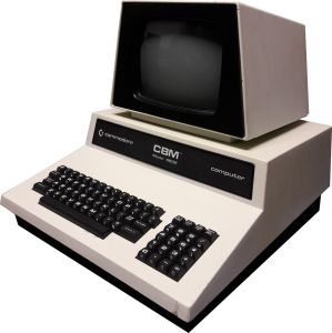 Side view of a PET 4032
 -
 A PET 4032 with the top lifted

Related pages
[edit | edit source]- Commodore PET 2001
- Commodore PET 4000 Series Maintenance Guide
- Commodore PET 4000 Series Troubleshooting Guide
- CRT Discharge Procedure
References
[edit | edit source]- ↑ 1.0 1.1 1.2 Commodore PET—link(accessed 2026-10-01) Section on the 4000 series: launched in 1980 with BASIC 4.0.
- ↑ 2.0 2.1 2.2 2.3 2.4 2.5 2.6 2.7 2.8 Commodore Business Machines, PET 4000 Series Technical Manual, P/N 990438, for models 4016 and 4032, hosted at Commodore PET 4000 Series Technical Manual. Drawing 8032090 Rev H, "PCB ASSY - UNIV. DYNAMIC PET" (PDF pp. 3-7): capacitors by reference designator and Commodore part number; voltage regulators VR1 (7905, -5 V 1.5 A, 901527-03, TO-220), VR2 (7812, +12 V 1 A, 901528-04, TO-3) and VR4 (LM323, 901528-01); 7.5 V zeners VR5 and VR6; 16 MHz crystal Y1; piezo transducer MT1 (907300-02). Drawing 8032051, "Power Supply Assy" (PDF p. 39): transformer, 23,000 µF capacitor, fuse 125 V slow-blow 1.6 A, fuse holder and rocker switch.
- ↑ 3.0 3.1 André Fachat, PET repairs—link(accessed 2026-10-01)