
Atari 65XE
The Atari 65XE is the 64 KB member of Atari Corporation's XE range, shown at the Winter Consumer Electronics Show in January 1985 as the cost-reduced replacement for the Atari 800XL. Atari's marketing manager described the redesign at the time as "engineering optimization" - the same machine made cheaper and more reliable through the use of fewer parts - and priced it at the pre-January 800XL price of US$100 to US$120.[1] Atari stated that the 65XE was 100% compatible with the 800XL it replaced.[2]
.jpg) | |
| Atari 65XE home computer | |
| Specifications | |
|---|---|
| Manufacturer | Atari Corporation |
| Type | Home computer |
| Released | 1985 (shown at the Winter CES, January 1985) |
| Intro price | US$100-120 at launch |
| CPU | MOS Technology 6502C @ 1.79 MHz (NTSC) / 1.77 MHz (PAL) |
| Memory | 64 KB RAM; 24 KB ROM (16 KB operating system + 8 KB Atari BASIC Rev. C) |
| Storage | Cassette (410/1010) or 5.25" floppy disk drive (1050/XF551) over SIO; ROM cartridge |
| Display | 40 x 24 text, up to 320 x 192 pixels |
| Sound | POKEY: four audio channels |
| OS / Firmware | Atari XE Operating System; Atari BASIC Rev. C in ROM |
| Predecessor | Atari 800XL |
| Successor | Atari 130XE |
| Model no. | 65XE |
Atari's field service manual for the XE line covers the 65XE directly: Section 2 carries the schematics and silkscreens for the CO70025, CA20097 and CA200519 65XE assemblies alongside the 130XE ones.[3]
Architecture and processor
editThe 65XE uses the 6502C at 1.79 MHz (NTSC) or 1.77 MHz (PAL) with the XE chipset: ANTIC (display processor, which also controls bus access and RAM refresh), GTIA (colour and luminance generation from ANTIC's bit stream, plus player/missile graphics), POKEY (audio, SIO control, controller scan and keyboard scan), the PIA (general purpose I/O), FREDDIE (memory controller, which also generates the clock signal to the CPU) and the memory management unit MMU1, Atari part C061618.[3]
The master oscillator is 14.31818 MHz on NTSC machines and 14.187576 MHz on PAL machines.[3]
Memory
edit- 64 KB RAM. On the CO70025 and CA20097 assemblies this is eight 64K x 1 (4164)
DRAMs; on the later CA200519 assembly it is two 64K x 4 (4464) DRAMs.[3]
- 24 KB ROM - a 16K x 8 operating system ROM plus 8 KB of Atari BASIC Rev. C. The
self-test memory screen represents the ROM as two 8 KB bars.[3]
Two operating-system ROM part numbers are documented for the XE line, C061598 and C300717. The difference is visible in the self test: a board fitted with C300717 shows four extra bars for the four 16 KB extended memory banks.[3] On a 65XE those extra bars have no RAM behind them - the extended banks are a 130XE feature.
Display, video output and sound
editVideo is produced by ANTIC and GTIA: text up to 40 x 24, bitmap modes up to 320 x 192 pixels, four players and four missiles with collision detection, and programmable display lists with hardware fine scrolling.
The 5-pin DIN monitor jack carries:[3]
| Pin | Signal |
|---|---|
| 1 | Monochrome (luminance) video output |
| 2 | Ground |
| 3 | Audio output |
| 4 | Composite video output |
| 5 | Colour (chrominance) output |
RF output is through a built-in modulator with a channel 2/3 switch; the modulated signal is 1-2 mV into 75 ohms.[3]
POKEY provides four audio channels, keyboard scanning, controller scanning and the SIO serial port.[3]
Input, output and expansion
edit- Cartridge slot - 30-pin edge connector[3]
- SIO port - 13-pin. Pin 1 clock in, 2 clock out, 3 data into CPU, 4 ground, 5 data out,
 6 ground, 7 command, 8 motor control, 9 proceed, 10 ready (computer on),
 11 audio in (175 mV), 12 not used, 13 interrupt[3]
- Two controller jacks - 9-pin D-type; pin 7 is +5 V, pin 8 ground[3]
- Monitor jack - 5-pin DIN
- RF output with channel 2/3 switch
- Power jack - 7-pin DIN
 | The SIO port on the XE machines carries no supply rail. Pin 10 is a "ready"
signal, not a +5 V output, and pin 12 is not used at all. Instructions to "check the +5 V and +12 V lines on SIO pins 10 and 12" describe something that does not exist on these machines.[3] |
The XE range dropped the XL's 50-pin Parallel Bus Interface. Its replacement, the Enhanced Cartridge Interface (ECI) - a 14-pin extension sitting behind the 30-pin cartridge connector - was announced as a 130XE-only feature.[2] The later CA200519 board assembly is shared between the 130XE and the 65XE/800XE, so individual machines vary; check the rear panel of the actual unit rather than assuming from the model name.[3]
Power
editThe 65XE takes +5 V DC through a 7-pin DIN power jack. The power jack, the power switch and the filtering are on the motherboard; everything else is in the external brick, which contains the step-down transformer (115 V or 230 V AC in, 9 V AC out), a bridge rectifier, an LM78S05 regulator, a 4700 uF reservoir capacitor and a 100 uF output capacitor. Atari rates the output at 5 V +/-5%, 1.5 A maximum.[3]
There is no rectifier, bridge or regulator on any XE motherboard. Descriptions of the XE power input as a "5.5 mm / 2.1 mm centre-positive barrel jack" are wrong for every machine in this range.[3]
Keyboard and self test
editThe XE keyboard is a full-stroke alphanumeric keyboard with a space bar and five function keys: HELP, START, SELECT, OPTION and RESET.[3]
- Holding OPTION while switching on disconnects the internal BASIC, and with no active
disk drive the self test runs.[3]
- HELP (or RESET) ends a looping self test and returns to the menu.[3]
The self test covers memory, audio/visual, keyboard, ports, ROM and RAM, and Atari's production test cartridge adds a numbered diagnostic error-code table - both are set out on the Atari 65XE Troubleshooting Guide.
Board assemblies
edit| Assembly | RAM | Notes |
|---|---|---|
| CO70025 | 8 x 4164 (64K x 1) | Schematic figure 2-7, silkscreen figure 2-8[3] |
| CA20097 | 8 x 4164 (64K x 1) | 65XEN; schematic figure 2-9, silkscreen figure 2-8[3] |
| CA200519 | 2 x 4464 (64K x 4) | Shared 65XE/800XE assembly; schematic figure 2-11, silkscreen figure 2-12[3] |
Gallery
edit-
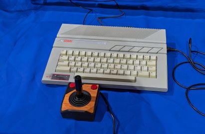 Atari 65XE
 -
 Rear panel
 -
 65XE main board


Service documentation
edit| Main board schematic | Field service manual |
|---|---|
| File:ATARI65XE-SCHEMATIC.pdf | File:Atari 130XE Field Service Manual.pdf |
The manual is also available as a page: Atari 130XE Field Service Manual. Despite its title it is the service manual for the whole XE range, including this machine.
Related pages
editReferences
edit- ↑ Tim Onosko and John J. Anderson, "Atari strikes back", Creative Computing Vol. 11 No. 3 (March 1985), p. 59, reproduced at atarimagazines.com. Contemporary report of the Winter CES 1985 line-up, written from briefings by Atari marketing manager Brian Kerr; source for the 65XE, 65XEM and XEP prices and the AMY specification quoted here.
- ↑ 2.0 2.1 Jack Powell, "130XE: How Atari's New 8-Bit Does It", Antic Vol. 4 No. 3 (July 1985), reproduced at atarimagazines.com. Atari's first published specification for the 130XE: bank-switching modes, the Enhanced Cartridge Interface signal list, and the 1.2 A at 5 V DC supply requirement.
- ↑ 3.00 3.01 3.02 3.03 3.04 3.05 3.06 3.07 3.08 3.09 3.10 3.11 3.12 3.13 3.14 3.15 3.16 3.17 3.18 3.19 3.20 3.21 Atari, 130XE Personal Computer Field Service Manual. Section 1 (theory of operation, chip pin assignments, external power supply schematic and rating, connector pinouts), Section 2 (schematics and silkscreens for all seven XE board assemblies), Section 3 (self test and production-test diagnostic error codes). Despite its title it covers the 65XE, the 800XE and the XE Game System as well. Hosted on this wiki: File:Atari 130XE Field Service Manual.pdf.