

Atari 130XE
.jpg) | |
| Atari 130XE home computer | |
| Specifications | |
|---|---|
| Manufacturer | Atari Corporation |
| Type | Home computer |
| Released | 1985 (shown at the Winter CES, January 1985) |
| CPU | Atari 6502C (SALLY) at 1.79 MHz (NTSC) or 1.77 MHz (PAL) |
| Memory | 128 KB RAM (64 KB main + 64 KB bank-switched) |
| Storage | Cassette and floppy drives on the SIO bus; ROM cartridge |
| Display | ANTIC and GTIA; 40 × 24 text, up to 320 × 192 pixels |
| Sound | POKEY, four channels |
| ROM | 24 KB: 16 KB operating system and 8 KB Atari BASIC Rev. C |
| Power | External 5 V DC supply (Atari C061982, 1.5 A) through a 7-pin DIN socket |
| OS / Firmware | Atari XL/XE operating system; Atari BASIC Rev. C in ROM |
| Predecessor | Atari 800XL |
| Model no. | 130XE |
The Atari 130XE is the 128 KB model of Atari Corporation's XE range of 8-bit computers. Creative Computing's report from Atari briefings before the January 1985 Winter CES described it as a 128K version of the Atari 65XE, unpriced at press time.[1] It has the XL architecture, the FREDDIE memory controller, a second 64 KB bank of RAM, and the Enhanced Cartridge Interface in place of the XL's Parallel Bus Interface.[2]
The 130XE was made in Taiwan and, late in production, in China, in NTSC, PAL and SECAM versions. The NTSC version has a channel 2/3 switch; the PAL version has none; the SECAM version has an FGTIA and PAL ANTIC, no television socket and a colour/monochrome switch.[2]
Hardware details below are from Atari's parts list for the 130XE,[3] from a 2016 reproduction of Atari's field service manual with redrawn schematics,[4] and from Sams' service data for the machine.[5]
Architecture and processor
[edit | edit source]The 130XE uses Atari's 6502C (SALLY), with a 16-line address bus giving direct access to 64 KB. The board carries the CPU, ANTIC, GTIA, POKEY, the PIA, FREDDIE, RAM and the operating system and BASIC ROMs.[4][3]
- ANTIC is the display processor and also controls bus access and RAM refresh.
- GTIA generates colour and luminance from ANTIC's display data.
- POKEY handles sound, serial I/O, the paddle inputs and keyboard scanning.
- The PIA is a general-purpose I/O chip for the controller ports; on the 130XE it also carries the bank-switching control bits.
- FREDDIE is the memory controller and generates the CPU clock from the master oscillator.
- The memory management unit (MMU, C061618) and a 3-to-8 decoder decode addresses; a gate array (C025953) decodes the extended memory.[4][3]
The master oscillator is 14.31818 MHz on NTSC machines and 14.187576 MHz on PAL machines; Atari's parts list gives both crystals and an oscillator module as alternatives.[3] The CPU runs at 1.7897725 MHz (NTSC) or 1.7734470 MHz (PAL).[2]
The address decoder takes A8–A15, ROM enable from the PIA, and refresh, and produces the selects for GTIA ($D0xx), the expansion connector ($D1xx), POKEY ($D2xx), the PIA ($D3xx), the cartridge ($D5xx), and the operating system ROM and RAM.[4]
Memory
[edit | edit source]RAM is 128 KB. On the original board it is sixteen 64K × 1 DRAMs (Atari C060612, 150 or 200 ns) at U9–U16 and U26–U33; the later cost-reduced board uses four 64K × 4 devices.[3][4] ROM is 24 KB: a 16K × 8 operating system ROM (U5) and 8 KB of Atari BASIC Rev. C (U4, C024947A).[3]
Bank switching
[edit | edit source]The extra 64 KB appears through a 16 KB window at $4000–$7FFF, controlled by four previously unused bits of the PIA's port B at $D301. Two bits select which of the four 16 KB pages of the second bank appears in the window; the other two, the video (ANTIC) bank enable and the CPU bank enable, decide which processor sees it. That gives four modes:[6]
| Mode | CPU sees | ANTIC sees |
|---|---|---|
| Compatibility | Main bank | Main bank |
| CPU extended RAM | A page of the second bank at $4000–$7FFF | Main bank |
| Video extended RAM | Main bank | A page of the second bank |
| Extended RAM | A page of the second bank | The same page of the second bank |
Sams gives the BASIC values: the normal value at 54017 ($D301) is 253, and POKE 54017 with 225, 229, 233 or 237 selects the first, second, third or fourth extended bank.[5] The manual reproduction notes that 48 KB is directly available to programs and more is accessible under DOS 2.5.[4]
Two operating system ROM part numbers appear in the documents: C061599 in Atari's parts list and C300717, which the FAQ's ROM list gives as OS revision 3 of 1 March 1985.[3][2] With the C300717 ROM the self test's memory screen shows four extra bars, one for each extended bank.[4]
Video and sound
[edit | edit source]Video comes from ANTIC and GTIA: text up to 40 × 24, bitmap modes up to 320 × 192 pixels, four players and four missiles with collision detection, display lists and hardware fine scrolling.
The 5-pin DIN monitor socket carries luminance on pin 1, ground on pin 2, audio on pin 3, composite video on pin 4 and chrominance on pin 5.[4][2] The RF modulator gives 1–2 mV into 75 Ω on channel 2 or 3.[4] The reproduction also gives a 5.5 MHz sound carrier, which is the PAL spacing; on NTSC channels 2 and 3 the spacing is 4.5 MHz, the figure in Atari's 800XL manual.[4][7]
Input, output and expansion
[edit | edit source]- Cartridge slot: 30-pin edge connector; +5 V is on pin 13.[4]
- Expansion connector (the Enhanced Cartridge Interface): a 14-pin edge connector behind the cartridge slot, carrying IRQ, HALT from ANTIC, A13–A15, ground, external select, reset, the $D1xx select, MPD from the MMU, audio in, refresh and +5 V (pin 7).[4] Atari said it provides "equivalent architectural functionality" to the XL's Parallel Bus Interface; it is not physically compatible.[6][2]
- SIO socket: 13-pin, up to 19,200 baud. On Atari's schematic pin 10 is +5 V/ready, fed from the +5A rail through ferrite bead L10 and decoupled by C79 (22 µF); pin 11 is audio in and pin 12 is not connected.[3][4][2]
- Two controller jacks: 9-pin D; pin 7 +5 V, pin 8 ground.[4]
- Monitor socket, RF output and power socket on the rear.
Power
[edit | edit source]The 130XE takes +5 V DC through a 7-pin DIN socket (J7, Atari C061838); pins 1, 4 and 6 are +5 V, pins 3, 5 and 7 are ground and pin 2 is the shield.[3][2] The board carries only the socket, the power switch and filtering; the transformer, rectifier and regulator are in the external supply.[4] Atari's supply for the XL and XE machines is part C061982, 5 V DC at 1.5 A.[3][2] Atari's first specification gave the 130XE's requirement as 1.2 A at 5 V DC, more than the 65XE because of the extra memory.[6]
Supply checks, the brick's internal circuit and the risks of failed supplies are on Atari 130XE General Maintenance#Power supply.
Keyboard and self test
[edit | edit source]The keyboard is full-stroke, with 62 keys and five function keys (HELP, START, SELECT, OPTION and RESET from left to right), connected to the board by a 24-conductor foil cable.[4] Holding OPTION at power-on disconnects the built-in BASIC; with no powered disk drive the machine then starts the self test.[2]
Atari's production test cartridge adds a numbered error-code list: 01–03 for ANTIC sync and interrupt faults, 04–10 for RAM and address decoding, 11 and 12 for POKEY, 34–39 for the serial and controller ports, and 71–73 for the cartridge and expansion connector test fixture. The full list is on Atari 130XE Troubleshooting Guide.[3]
Board assemblies
[edit | edit source]| Assembly | RAM |
|---|---|
| CO70065 / CO70067 | 16 × 4164 (64K × 1) |
| CO70050 / CO70052 rev. 2 | 16 × 4164; SECAM version |
| C103579-001 / CA200519 | 4 × 4464 (64K × 4) |
Atari's own drawings, bound with its parts list, are the schematic C070065 (revision B, for NTSC and PAL machines), the board C070067 and the board assembly CA070012.[3] The reproduction warns that minor design variations occur with production date.[4]
Gallery
[edit | edit source]-
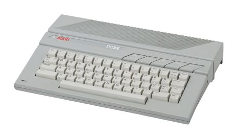 Atari 130XE
 -
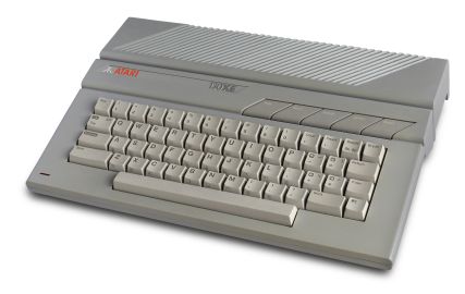 Atari 130XE

Service documentation
[edit | edit source]- Atari 130XE Parts List and Production Test Instructions: Atari's 1985 parts list, 1986 production test instructions and error codes, and the Atari (Japan) schematic C070065 and board drawings
- Atari 130XE Field Service Manual: the 2016 reproduction of Atari's field service manual, with redrawn schematics for the whole XE range
- Sams Computerfacts Atari 130XE: Sams CC16, with measured schematics and service checks
Related pages
[edit | edit source]- Atari 130XE General Maintenance
- Atari 130XE Troubleshooting Guide
- Atari 130XE Capacitor Replacement Guide
- Atari 65XE
- Atari 800XE
- Atari XE Game System
References
[edit | edit source]- ↑ Tim Onosko and John J. Anderson, "Atari strikes back", Creative Computing vol. 11 no. 3 (March 1985), p. 59, reproduced at atarimagazines.com. Report of Atari's Winter CES 1985 line-up from briefings by Atari marketing manager Brian Kerr; source for the 130XE being unpriced at press time.
- ↑ 2.00 2.01 2.02 2.03 2.04 2.05 2.06 2.07 2.08 2.09 Michael Current (ed.), Atari 8-Bit Computers: Frequently Asked Questions, last modified 29 November 2009, section 1.8 "What is the Atari 130XE?", section 1.16 (port pinouts) and the power supply list. Text at faqs.org. Community reference.
- ↑ 3.00 3.01 3.02 3.03 3.04 3.05 3.06 3.07 3.08 3.09 3.10 3.11 Atari (U.S.) Corp., 130XE Reference Manual (cover dated March 1990), containing the 130XE Parts List of 25 June 1985 (4 pages), the XE/XL Production Test Operator's Instructions and Diagnostic Error Codes, Rev. 3.4, 22 May 1986, and Atari (Japan) Corporation drawings: schematic diagram C070065 Rev. B (130XE NTSC/PAL, revised per ECO 00259, 1986), PCB C070067 Rev. A and PCB assembly CA070012 Rev. A. Hosted on this wiki as Atari 130XE Parts List and Production Test Instructions (PDF).
- ↑ 4.00 4.01 4.02 4.03 4.04 4.05 4.06 4.07 4.08 4.09 4.10 4.11 4.12 4.13 4.14 4.15 4.16 130XE Personal Computer Field Service Manual, reproduction by JER/Eightbitter (PDF author "Jurek"), November 2016. The text is retyped from Atari's field service manual and extended to the 65XE, 800XE and XE Game System; the schematics and silkscreens for seven XE board assemblies were redrawn in May 2014 because the original copies were in poor condition. It is not an Atari publication. Section 1 (theory of operation, pin assignments, external power supply, connector pinouts), section 2 (schematics), section 3 (self test). Hosted on this wiki as Atari 130XE Field Service Manual (PDF).
- ↑ 5.0 5.1 Howard W. Sams & Co., Sams COMPUTERFACTS CC16, Atari Model 130XE, service checks (p. IV), disassembly and adjustments (p. V), parts list. Hosted on this wiki as Sams Computerfacts Atari 130XE (PDF).
- ↑ 6.0 6.1 6.2 Jack Powell, "130XE: How Atari's New 8-Bit Does It", Antic vol. 4 no. 3 (July 1985), reproduced at atarimagazines.com. Atari's first published specification for the 130XE: bank-switching modes, the Enhanced Cartridge Interface, and the 1.2 A at 5 V DC supply requirement.
- ↑ Atari, Inc., 800XL Computer Field Service Manual, FD100740 Rev. 01, February 1984, p. 1-10 (RF modulator: audio sound carrier frequency 4.5 MHz; channel 2 video carrier 55.25 MHz, channel 3 61.25 MHz). Hosted here as Atari 800XL Computer Field Service Manual.