

Atari TT030
 | |
| Atari TT030 with keyboard, mouse and an NEC MultiSync monitor | |
| Specifications | |
|---|---|
| Manufacturer | Atari Corporation (built by Atari Taiwan Manufacturing Corp., later EFA Corporation) |
| Type | Desktop workstation |
| Released | 24 August 1990 (West Germany); 12 November 1990 (United States) |
| Discontinued | November 1993 |
| Intro price | DM 6,498 with TTC1434 monitor (August 1990); US$2,998 (TT030/2-50, November 1990) |
| CPU | Motorola MC68030 at 32 MHz |
| Memory | 2 MB dual-purpose (ST) RAM on the main board; Atari daughterboards add 2 or 8 MB ST RAM and 4 or 16 MB TT RAM (26 MB in all) |
| Storage | 3.5-inch floppy drive (720 KB, 1.44 MB on later machines); optional internal SCSI hard disk |
| Display | ST modes 320 × 200 (16 colours), 640 × 200 (4), 640 × 400 (mono); TT modes 320 × 480 (256), 640 × 480 (16), 1280 × 960 (mono, ECL monitor); palette 4,096 colours |
| Sound | Yamaha YM2149 PSG and stereo 8-bit DMA sound, through an LMC1992 volume and tone control |
| ROM | 512 KB in four socketed 1 Mbit ROMs (TOS 3.01, 3.05, 3.06) |
| FPU / coprocessor | Socketed Motorola MC68881, replaceable with an MC68882 |
| Ports / interface | SCSI, ACSI, floppy, parallel, four serial ports, LAN, MIDI in and out, cartridge, VGA/ECL monitor, stereo audio |
| Expansion | One VMEbus slot (single Eurocard, A24/D16 and A16/D16) |
| Power | Internal 64 W switching supply, 100–240 V AC |
| OS / Firmware | TOS 3 |
| Model no. | TT030/2-50, TT030/4-50, TT030/6-50, TT030/8-80 |
The Atari TT030 is a 68030 desktop computer made by Atari Corporation from 1990 to 1993. It keeps compatibility with the ST and Mega machines and adds a 32 MHz MC68030, a floating-point coprocessor, new video modes up to 1280 × 960, a SCSI port, extra serial ports, a LAN port and a VMEbus slot.[1][2] Atari's June 1990 hardware reference describes it as the first of a new series intended to run both TOS and Unix.[3]
History
[edit | edit source]According to the Atari Computermuseum, Atari first showed a TT prototype privately at CeBIT in Hannover in March 1988, still with a 68020 and a planned port of AT&T Unix System V by UniSoft. A 68030 prototype running a modified TOS 1.04 followed at CeBIT in March 1989, and the machine was shown to the public at the Atari Messe in Düsseldorf in August 1989, then with a 16 MHz processor, a 30 MB hard disk and 2 MB of RAM. The US debut was at COMDEX in November 1989.[4]
The launch planned for May 1990 was held back so that the processor clock could be raised from 16 to 32 MHz. The TT030 went on sale at the Atari Messe on 24 August 1990 with 2, 4, 6 or 8 MB of RAM and a 48 MB hard disk; in Germany the TT030/2-50 with the TTC1434 colour monitor cost DM 6,498. Sales in the United States began on 12 November 1990 under an FCC Class A (commercial) certificate, at US$2,998 for the TT030/2-50, and Class B certification for home use followed in January 1993.[4]
A revised model appeared in September 1991. In it the whole system ran at 32 MHz, where the earlier machines ran only the processor and coprocessor at that speed. It also had a high-density floppy drive, and a conductive coating sprayed inside the case where the earlier model had steel shielding.[4] The Unix version announced as the TT030/X and the TT/X tower never shipped as such; in August 1992 Atari said it would no longer produce a Unix port for the TT. Production ended in November 1993.[4]
Hardware
[edit | edit source]Processor, coprocessor and ROM
[edit | edit source]The CPU is an MC68030 clocked at 32 MHz, with its paged memory management unit and separate instruction and data caches. The floating-point coprocessor is clocked at 32 MHz with the CPU; Atari's text describes a socketed MC68881 that can be replaced with the faster MC68882;[2][3] the July 1991 schematic in the service manual shows the coprocessor position, U101, as an MC68882 in a PLCC package.[5] The June 1990 hardware reference still gives the CPU clock as 16 MHz; the August 1991 service manual gives 32 MHz.[3][2]
TOS is held in four 1 Mbit ROMs in 32-pin sockets, 512 KB in total. The system bus reads all four at once, so all four must be fitted.[2] Jumpers W601–W603 set the ROM type (27256, 27512, 1 Mbit EPROM or mask ROM).[6] The Atari Computermuseum lists TOS 3.01 in machines built until December 1990, 3.05 until September 1991 and 3.06 after that.[4]
Memory
[edit | edit source]The main board carries 2 MB of dual-purpose RAM, used by the system and by the video, made of sixteen 256K × 4 100 ns DRAMs. The video logic sees it as 64 bits wide and the processor as 32 bits, with access interleaved in 250 ns slots.[2] Atari's daughterboards add 2 or 8 MB of dual-purpose ST RAM, and 4 or 16 MB of single-purpose TT RAM that only the processor uses; with both, the machine has 26 MB.[1][2] The 2/8 MB ST RAM board (CA401059) carries sixteen DRAMs and its own 144-pin MCU.[7] VME memory cards can also be used, with an extra wait state.[2] Larger TT RAM boards from other makers, including ones that take 72-pin SIMMs, use more of the TT RAM address space.[4]
Video
[edit | edit source]Display memory is 32,000 bytes in the ST modes and 153,600 bytes in the TT modes, and can start anywhere in dual-purpose RAM. The modes are:[2][3]
| Mode | Resolution | Colours |
|---|---|---|
| ST low | 320 × 200 | 16 of 4,096 |
| ST medium | 640 × 200 | 4 of 4,096 |
| ST high | 640 × 400 | 2 (duochrome) |
| TT low | 320 × 480 | 256 of 4,096 |
| TT medium | 640 × 480 | 16 of 4,096 |
| TT high | 1280 × 960 | Monochrome, ECL monitor only |
The monitor connector is a 15-pin D type for VGA-type colour monitors or the ECL monochrome monitor; pin 9 is the monochrome detect line. The MCU can be set for 50, 60 or 71 Hz operation.[2] Atari's own monitors were the TTC1434 colour and TTM195 monochrome.[8] There is no blitter; the Atari Computermuseum notes that Atari judged the ST's blitter too slow for the TT and did not design a 32-bit one.[4]
Sound
[edit | edit source]The YM2149 programmable sound generator, clocked at 2 MHz, is mixed with a two-channel 8-bit DMA sound system that the hardware reference describes as the same as the STE's. Both go through an LMC1992 volume and tone control to an internal speaker and to two RCA jacks on the back panel.[2][3]
Ports and expansion
[edit | edit source]| Position | Connector | Notes |
|---|---|---|
| Front | Floppy drive, optional hard disk | Each with its own busy LED |
| Left side | Reset button; LAN (8-pin mini-DIN); MIDI Out; MIDI In; ROM cartridge (40-pin edge); keyboard (6-pin telephone-style jack) | MIDI Out also carries MIDI Thru; the cartridge port takes ST cartridges |
| Rear | SCSI (DB-25); external floppy (14-pin DIN); ACSI hard disk (DB-19); printer (DB-25); monitor (15-pin D); VME slot; Modem 1 and Modem 2 (DB-9P); power switch and mains inlet; fan; Audio L and Audio R (RCA) | |
| Keyboard | Two DB-9 ports, one on each side | The left port takes a joystick only; the right takes a mouse or joystick |
Sources: Atari's case views and interface sections,[1][2] connector types from the Atari Computermuseum.[4]
The serial ports come from two 68901 MFPs and a Z85C30 SCC. One SCC channel can be switched by software between the LAN connector and an RS-232 port.[2][3] SCSI uses an NCR 5380 on a single-ended bus at up to 4 MB/s, with an internal 50-pin cable; the factory hard disk is SCSI ID 0. The ACSI port and the floppy share the ST-compatible DMA channel.[2]
The VMEbus slot is to revision C.1 and takes one single-height Eurocard. The main board acts as the VMEbus system controller and supplies a 16 MHz system clock that is independent of the processor speed.[3]
The keyboard has its own HD6301 processor and talks to an MC6850 ACIA at 7,812.5 bit/s; MIDI uses a second 6850 at 31.25 kbaud.[2] The real-time clock is an MC146818A with 50 bytes of battery-backed RAM, kept running by a 3.6 V lithium cell when the machine is off.[2][3]
Power supply
[edit | edit source]The internal switching supply is rated at 64 W from 100–240 V AC at 2 A, 50/60 Hz, with four outputs:[1]
| Rail | Current |
|---|---|
| +5 V | 7 A |
| +12 V | 2 A |
| −5 V | 0.4 A |
| −12 V | 0.3 A |
Atari's parts list gives the supply as a Phihong PSM 5341, part number C302074-001. It replaced the earlier Phihong unit C301379-001 under an engineering change of 21 November 1990.[7] All four rails and a Power Good line reach the main board on connector J100.[9]
Board revisions
[edit | edit source]The Atari Computermuseum describes the first machines as having the 32 MHz processor and coprocessor on a card plugged into the CPU socket, with the rest of the system at 16 MHz, and the September 1991 revision as running the whole system at 32 MHz.[4] Atari's documents in the service manual are for main board assembly CA400770, PCB TT030 32 MHz, whose schematic is drawing C301762-001, titled TT030/32. Jumper W101 on that board selects 32 MHz (1–2, the default) or 16 MHz (2–3).[6][7]
The assembly drawing also lists three factory rework procedures. ECO 1269 bonds the ground planes together on the solder side. ECOs 1322 and 1323 cut tracks and add jumper wires between the MCU, the DMA controllers and their support logic (74F04, 74LS74 and 74LS86 gates), and ECO 1323 also covers fuse F61 and ferrite bead L601 with insulating tubing and tape, so that they cannot short to the power supply's mounting foot.[6]
The floppy controller was originally a WD1772. Atari's 1.44 MB upgrade kit replaces it at U409 with the AJAX controller, fits TOS 3.06 and sets segment 7 of switch J203.[10]
Maintenance and repair
[edit | edit source]The clock cell is a 3.6 V lithium cell, Atari part C301020-001, rated 400 mAh.[7] Atari's service manual includes a dead-unit procedure that uses an RS-232 terminal and the TT diagnostic cartridge, the cartridge's error codes, a symptom checklist and disassembly steps.[8] See:
Documentation
[edit | edit source]- Atari TT030 Computer Field Service Manual, C302483-001, August 1991: theory of operation, testing, disassembly, symptom checklist, parts lists, schematics and silkscreen.
- Atari TT030 Hardware Reference Manual, June 1990: developer-level description of the hardware and its memory, I/O and interrupt map.
- Atari TT030 Schematic, drawing C301762-001: the twelve-sheet main board schematic.
- Atari TT030 1.44MB Floppy Disk Drive Installation Manual, C302563-001, 1991.
Gallery
[edit | edit source]-
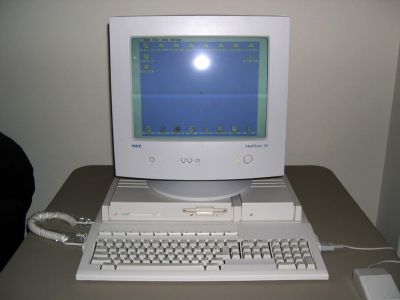 TT030 with keyboard and monitor
 -
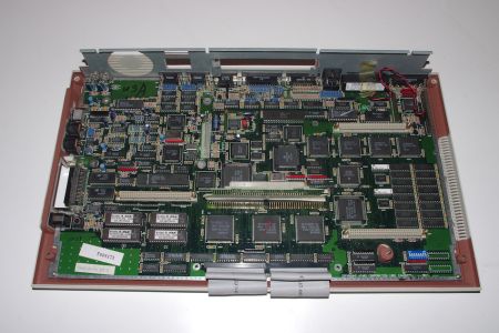 Main board of a US machine, in the lower case
 -
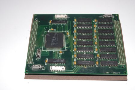 Atari 2 MB ST RAM board with its MCU
 -
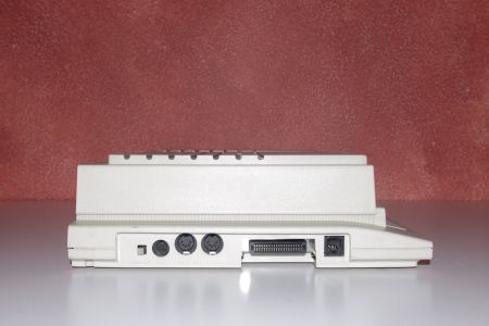 Left side: reset, LAN, MIDI, cartridge and keyboard sockets
.jpg)
.jpg)
.jpg)
Related pages
[edit | edit source]- Atari TT General Maintenance
- Atari TT Troubleshooting Guide
- Atari TT Capacitor Replacement Guide
- Atari Mega STE
- Atari Falcon030
References
[edit | edit source]- ↑ 1.0 1.1 1.2 1.3 Atari Corporation, Atari TT030 Computer Field Service Manual, part number C302483-001, August 1991, section 1, pp. 1–3 (PDF pp. 8–10): overview, main components, case design (front, left side and rear views), power supply rating. Hosted as Atari TT030 Computer Field Service Manual (PDF).
- ↑ 2.00 2.01 2.02 2.03 2.04 2.05 2.06 2.07 2.08 2.09 2.10 2.11 2.12 2.13 2.14 Atari Corporation, Atari TT030 Computer Field Service Manual, C302483-001, August 1991, section 2, pp. 4–25 (PDF pp. 11–32): 2.1 overview and display modes; 2.2.1 processor; 2.2.2 coprocessor; 2.2.3 ROM; 2.2.4 RAM and memory map; 2.2.8 MCU; 2.2.9 real-time clock; 2.3.1 video and monitor connector; 2.3.2 audio; 2.4 MIDI, SCSI, floppy, SCC, MFP, parallel, keyboard, mouse and joystick, cartridge and VMEbus. Hosted as Atari TT030 Computer Field Service Manual.
- ↑ 3.0 3.1 3.2 3.3 3.4 3.5 3.6 3.7 Atari Corporation, Atari TT030 Hardware Reference Manual, June 1990. Section I, introduction and feature list (PDF pp. 4–5); II.1 processor; II.2 floating-point coprocessor; II.3 ROM (PDF p. 6); III.9 sound (PDF p. 19); IV VMEbus (PDF p. 20). Hosted as Atari TT030 Hardware Reference Manual (PDF).
- ↑ 4.0 4.1 4.2 4.3 4.4 4.5 4.6 4.7 4.8 Atari Computermuseum, "Der Atari TT und seine Verwandten", https://www.atari-computermuseum.de/tt030.htm (in German; last edited 20 August 2024; retrieved 2026-10-01). History, models, chip list, interface table, technical data and prices.
- ↑ Atari Corporation, TT030/32 schematic, drawing C301762-001, twelve sheets dated 1 July 1991, reproduced in the Atari TT030 Computer Field Service Manual, C302483-001, section 8 (PDF pp. 114–125). Sheet 1 (PDF p. 114): MC68030 U100, MC68882 U101; sheet 3 (p. 116): keyboard connector J302 and fuse F31 0.5 A; sheet 4 (p. 117): MC146818A U401 and clock battery connector J400; sheet 6 (p. 119): cartridge port J601, fuse F61 5.0 A, ferrite bead L601.
- ↑ 6.0 6.1 6.2 Atari Microsystems Corporation, Assy. Drawing, TT030 32 MHz, drawing CA400961, 16 May 1991, reproduced in the Atari TT030 Computer Field Service Manual, section 8 (PDF p. 112): rework procedures for ECOs 1269, 1322 and 1323; insulation of F61 and L601; floppy-drive DIP switch settings; jumper W101 (32 MHz 1–2 default, 16 MHz 2–3) and ROM-type jumpers W601–W603.
- ↑ 7.0 7.1 7.2 7.3 Atari Corporation, Atari TT030 Computer Field Service Manual, C302483-001, section 7, parts list (PDF pp. 87–101). PDF p. 92: Assy ST RAM 2/8 MB CA401059 Rev C, 16 July 1991 (sixteen 256K × 4 or 1M × 4 DRAMs; custom MCU, 144-pin, ST4133, at U12; two 100 µF 16 V axial electrolytics, C23 and C24). PDF p. 99: ECO history of the main assembly, including ECO 3005, 21 November 1990, "change PSU Phihong from C301379-001 to C302074-001". PDF pp. 100–101: Assy main w/o HDD TT030/2 CA400416, 4 April 1991, listing assembly CA400770 PCB TT030 32 MHz for each country, C302074-001 PSU Phihong PSM 5341 and C301020-001 Battery lithium 3.6 V 400 mAh.
- ↑ 8.0 8.1 Atari Corporation, Atari TT030 Computer Field Service Manual, C302483-001, section 3, pp. 29–35 (PDF pp. 36–42): test equipment, test configuration, troubleshooting a dead unit, diagnostic cartridge (ROM Rev 1.4) and power-up error codes.
- ↑ Atari Corporation, TT030/32 schematic, drawing C301762-001, twelve sheets, earlier issue (sheet 8 dated 7 May 1990), engineer John Horton. Sheet 1: 68030 (U100), coprocessor (U101), power connector J100 and its capacitors, power-on (J103) and auxiliary fan (J102) headers. Hosted as Atari TT030 Schematic (PDF).
- ↑ Atari Corporation, Atari TT030 1.44MB Floppy Disk Drive Installation Manual, part number C302563-001, 1991, pp. 1–4: kit CA401220-001 contents and installation steps. Hosted as Atari TT030 1.44MB Floppy Disk Drive Installation Manual (PDF).