
IBM PC (5150) Capacitor Replacement Guide
The IBM 5150 motherboard carries through-hole tantalum capacitors that fail short-circuit and latch the PSU off, producing what looks like a dead motherboard. Recapping the motherboard and PSU is the single most useful preventative job on a 40-plus-year-old 5150. This guide documents what is actually known about the 5150's capacitor layout from primary sources (the IBM 5150 Technical Reference and the long-running minuszerodegrees.net failure-tracking work) rather than speculative per-designator tables.
Visual Inspection & Failure Signs
Before doing any soldering work, examine each board under good light:
- Cracked or discoloured tantalum capacitors — small yellow or orange dipped beads. Failed tantalums sometimes show no visual indication at all; in other cases, a small black eye/hole is visible on the body (see minuszerodegrees.net's failure-mode photo gallery).
- Burned-out resistor next to a capacitor — a tantalum that shorted may have taken out the series resistor on its rail.
- Brown halo around capacitor pads — conductive residue from a long-failed capacitor.
- Sharp electrolyte / "burnt" smell — recent tantalum venting.
If any tantalum is visibly damaged, replace it.
IBM 5150 Motherboard Tantalum Capacitors (verified)
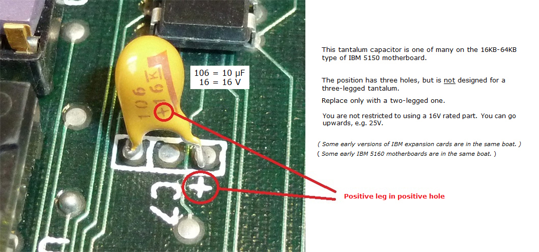
The 5150 motherboard uses tantalum capacitors of value 10 µF / 16 V. IBM designated many of the tantalum positions with the shared designator C7 on the silkscreen — multiple physical capacitors carry the same C7 designator. The exact count differs between the two motherboard revisions:
| Motherboard revision | Total tantalums on the board | On the +5 V line | On the +12 V line | All other positions |
|---|---|---|---|---|
| 16KB-64KB (early) | 17 | 6 (all marked C7) | 5 (all marked C7, 10 µF / 16 V) | the remainder |
| 64KB-256KB (later) | 13 | 10 (all marked C7) | 1 (filter for expansion-slot +12 V; not critical to motherboard operation) | the remainder |
The motherboard also has 23 ceramic decoupling capacitors of value 0.047 µF (marked C3, "K5M"-coded yellow ceramic). Ceramic capacitors very rarely fail; they do not need preventative replacement.
For per-position photographs of the +5 V and +12 V tantalums on each motherboard revision, see minuszerodegrees.net's +5 V short-circuit guide and +12 V short-circuit guide, which include annotated board photos.
On the 16KB-64KB motherboard, four of the five +12 V tantalums sit together as a group and are important to the operation of the on-board RAM. Replace all five with new 10 µF / 16 V parts.
On the 64KB-256KB motherboard, the single +12 V tantalum filters only the +12 V going to the expansion slots. The motherboard will operate without it — if it is short-circuit, it can be removed entirely (though the recommended action is to replace it with a new 10 µF / 16 V part).
Replacement Parts
For replacement of the motherboard tantalums, use one of:
- Modern tantalum: 10 µF / 16 V tantalum bead (e.g. KEMET T350).
- Solid polymer tantalum: KEMET T491 series, 10 µF, 16 V or higher.
- Pre-packaged cap kit: Console5 sells IBM-specific cap kits.
Whichever type is used, observe polarity: the positive lead (longer, marked +) goes into the positive-marked hole on the PCB. See minuszerodegrees.net's polarity reference photo for a confirmed example.
Soldering Notes
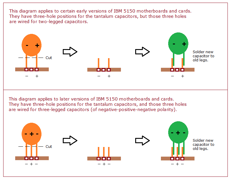
The 5150 motherboard has heavy copper pours on the ground and power planes that make conventional soldering iron work difficult. Direct soldering with an under-powered iron risks lifting pads. minuszerodegrees.net documents a "snip, cut, tin, overlap" technique that works around this — see the SNCTOL diagram for the 5150 motherboard.
If using a soldering iron, set it to at least 380 °C and use plenty of flux. A hot-air rework station, where available, makes the job substantially easier.
Capacitor Replacement Procedure
- Disassemble. Disconnect mains, remove the five rear cover screws, slide the cover off. Unplug P8/P9 from the motherboard. Remove all ISA cards and the floppy/HDD ribbon cables, labelling each. Remove the four PSU mounting screws and lift the PSU out.
- Bleed the PSU bulk capacitors. The primary-side bulk capacitors retain a dangerous charge for hours after disconnection. Discharge each through a 10 kΩ resistor across the leads for at least 30 seconds, then verify with a multimeter.
- Document the original capacitor layout with photographs.
- Desolder tantalums one at a time. Snip the leads close to the body and lift the body off, then desolder the remaining leads from the pad side. This avoids stressing the pads.
- Install replacements with correct polarity.
- Clean up flux residue with isopropyl alcohol; inspect for solder bridges.
- Reassemble, power on with no ISA cards beyond the video adapter, and confirm PSU rails before fitting other cards.
ISA Card Capacitors
Several common 5150-era expansion cards also carry tantalum capacitors that fail in the same way as the motherboard tantalums:
- IBM Monochrome Display Adapter — one or more tantalum capacitors on the +5 V rail.
- IBM Color Graphics Adapter — tantalum capacitors near the video output buffers.
- IBM FDD Adapter — tantalum on the +5 V rail near the floppy controller.
- IBM Fixed Disk Adapter — tantalum + electrolytic mix near the BIOS expansion ROM.
If a card causes the PSU to latch off when plugged in, but the motherboard alone runs cleanly, suspect a short-circuit tantalum on that card.
PSU Capacitor Replacement
The IBM 5150 PSU (Type 1, 63.5 W; Type 2, 130 W) uses standard wet-electrolytic capacitors on the secondary side and X/Y safety-rated capacitors on the primary side. Both types of PSU benefit from a full recap, with particular attention to:
- Primary-side bulk filtering — high-voltage electrolytics on the rectified-mains side.
- Output filters for +5 V, +12 V, −5 V, −12 V.
- X / Y safety capacitors on the mains input — must be replaced with safety-rated parts (X2 / Y1 / Y2 as appropriate), never with generic film capacitors.
Specific values vary between PSU manufacturers (Astec, Zenith, IBM-branded variants). Consult the markings on the existing capacitors before ordering replacements; a third-party PSU recap kit such as Console5's covers the standard 5150 PSU.
The three BUV46 switching transistors in the PSU are a known failure point. If any one tests faulty, replace as a matched set.
Post-Recap Voltage Checks
After recapping, with the machine running and no ISA cards fitted beyond the video adapter, verify the PSU rails at P8/P9 are within the ranges in the maintenance guide voltage table. Ripple under 100 mV peak-to-peak is acceptable on +5 V; under 200 mV on +12 V.
References
- Tantalum capacitor short-circuit on the +5 V line, minuszerodegrees.net.
- Tantalum capacitor short-circuit on the +12 V line, minuszerodegrees.net.
- IBM 51xx tantalum capacitor replacement details, minuszerodegrees.net.
- IBM, IBM 5150 Technical Reference (6025005, August 1981) — schematics.
- Console5 IBM cap kits.