
IBM 5153
The IBM 5153, which IBM called simply the IBM Color Display, is the RGBI colour monitor IBM introduced in March 1983 to pair with the Color/Graphics Monitor Adapter (CGA). It is the reference monitor for CGA: the colours that CGA software was written against are the colours a 5153 produces.
| IBM Color Display | |
|---|---|
 |
|
| IBM monitors, left to right: 5151 monochrome, 5153 colour, 5154 Enhanced Color Display | |
| Manufacturer | IBM |
| Type | TTL RGBI colour CRT monitor |
| Release date | March 1983 |
| Interface | TTL RGBI, 9-pin D-shell (driven by the IBM Color Graphics Adapter) |
| Compatible | IBM PC (5150), IBM PC XT (5160), IBM PC AT (5170), CGA-compatible systems |
| Dimensions | 297 mm H × 392 mm L × 407 mm D |
| Weight | 11.8 kg (26 lb) |
| Model | 5153 |
Display Characteristics
editIBM's own figures:[1]
- CRT: 340 mm (13-inch), high-contrast (black) screen.
- Presentation: 80 characters wide by 25 rows deep, characters defined in an 8 PEL high by 8 PEL wide matrix.
- Colour: up to 16 colours when driven by the Color/Graphics Monitor Adapter. Red, green and blue signals and intensity are independent digital lines.
- Vertical drive: positive synchronous, TTL-compatible, 50/60 Hz, non-interlaced.
- Horizontal drive: positive-level, TTL-compatible, at 15.75 kHz.
- Heat output: 240 BTU/hr. Power cable 1.83 m, signal cable 1.5 m.
- Controls: power switch, power indicator, brightness and contrast on the front panel; vertical hold and vertical size on the rear panel.
Measured at the adapter, CGA horizontal sync is a 4 µs positive-going pulse every 63.7 µs and vertical sync is a 190 µs positive-going pulse every 16.7 ms.[2]
Unlike the IBM 5151, the 5153 has its own mains cable and its own power switch. Its internal supply switches automatically between 120 V 60 Hz and 220 V 50 Hz.[1]
Colour Behaviour
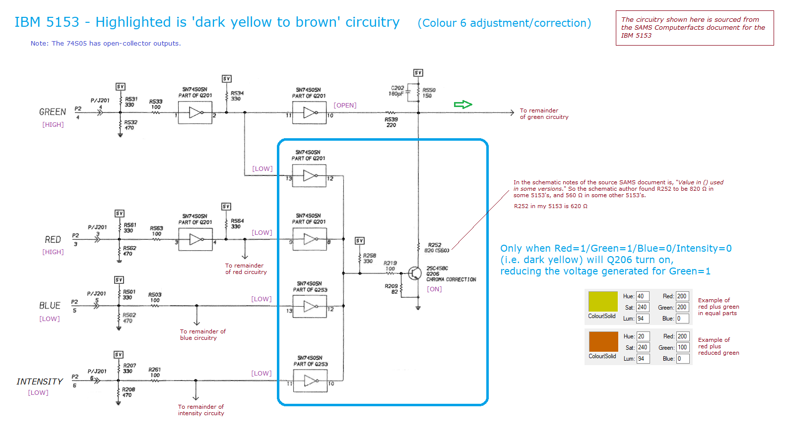
editCGA's 16-colour set is produced by four digital lines, so in principle colour 6 (red + green, low intensity) would be a dark yellow. On an IBM 5153 it appears as brown, because the monitor contains circuitry that attenuates the green drive for that specific combination. IBM's own CGA documentation names the low-intensity graphics palette "green/red/brown" rather than green/red/yellow, which is the adapter's side of the same convention.[3] minuszerodegrees.net publishes the relevant portion of the 5153's schematic as its "dark yellow to brown" circuitry.[4]
Third-party RGBI monitors that drive all three guns with equal gain show a dark yellow in that position instead. That difference is the single most visible reason a CGA machine can look wrong on a non-IBM monitor.
Input Connector
editA 9-pin D-shell carrying TTL RGBI.[3]
| Pin | Signal |
|---|---|
| 1 | Ground |
| 2 | Ground |
| 3 | + Red |
| 4 | + Green |
| 5 | + Blue |
| 6 | + Intensity |
| 7 | Not used |
| 8 | + Horizontal sync |
| 9 | + Vertical sync |
Pin 7 being physically absent from the plug is normal — it is unused in the CGA standard.[5]
Common Faults
edit- Stiff brightness and contrast knobs. Known behaviour, probably deliberate. Not a fault.[5]
- A white horizontal line just below the top of the raster. A known defect of the design rather than a component failure, and correctable; the vertical-scan fix is documented in the Sams service data.[5]
- No picture and no raster. Check the ac supply and the supplies derived from the horizontal output transformer T401 before anything else.[6]
- Raster present, no picture. Check the source voltages generated from T401.[6]
- No raster at all but the set is alive. Check the EHT rectifier, which is part of T401.[6]
- No vertical deflection, or poor vertical linearity and foldover. Inject a vertical signal and work through the vertical driver Q301, the vertical output transistors Q302 and Q303, the electrolytic C315 and the vertical winding; linearity and foldover faults usually sit in the vertical feedback and bias network.[6]
- One colour missing. Work the chroma stage and that colour's output stage; a dry joint at the 9-pin connector produces the same symptom and is much more common.[6]
- Geometry that drifts as the set warms up. Ageing electrolytics on the chassis board. See Capacitor Failure Symptoms.
CRT Safety
editThe 5153 is mains-powered and its CRT retains a lethal anode charge after the set is unplugged. IBM's own schematic sheet carries the warning that hazardous voltages of up to 450 V exist on the printed circuit boards.[1] Discharge the tube before working inside — see CRT Discharge Procedure.
References
edit- ↑ 1.0 1.1 1.2 IBM, IBM Color Display, part 6361470, Options and Adapters section, Personal Computer Hardware Reference Library — hosted on this wiki as File:IBM Options and Adapters - IBM Color Display (5153).pdf. "Description" and "Specifications": the 340 mm (13-inch) CRT, the display's own auto-switching 120 V 60 Hz / 220 V 50 Hz supply, the 1.5 m direct-drive signal cable, 80 characters by 25 rows with characters defined in an 8 PEL high by 8 PEL wide matrix, independent red, green, blue and intensity video signals, positive synchronous TTL vertical drive at 50/60 Hz non-interlaced, positive-level TTL horizontal drive at 15.75 kHz, the front and rear panel controls, and the physical specifications quoted here. The logic diagram carries IBM's warning that voltages up to 450 V exist on the printed circuit boards. Also documented here as IBM Options and Adapters - IBM Color Display.
- ↑ IBM: MDA / CGA / EGA, minuszerodegrees.net. Source for the side-by-side 9-pin assignments and for the measured sync pulse shapes: MDA, an 8 us positive-going horizontal pulse every 54.3 us and an 850 us negative-going vertical pulse every 20 ms; CGA, a 4 us positive-going horizontal pulse every 63.7 us and a 190 us positive-going vertical pulse every 16.7 ms.
- ↑ 3.0 3.1 IBM, IBM Color/Graphics Monitor Adapter, part 6361509, Options and Adapters section, Personal Computer Hardware Reference Library — hosted on this wiki as File:IBM Options and Adapters - IBM Color Graphics Monitor Adapter.pdf. Source for the Motorola 6845 CRT controller, the 16 KB display buffer without parity, the three video interfaces and the light pen interface, the 8 wide by 8 high character box and the two jumper-controlled fonts, the alphanumeric and all-points-addressable modes, non-interlaced operation at 7 or 14 MHz, and the mode-control, colour-select and status register definitions — including colour-select bit 5, which selects green/red/brown when 0 and cyan/magenta/white when 1, and bit 4, which selects the intensified alternate set. Also documented here as IBM Options and Adapters - IBM Color Graphics Monitor Adapter.
- ↑ IBM 5153 — Dark yellow to brown circuitry, minuszerodegrees.net. Extract from the 5153 schematic showing the circuitry inside the monitor that turns the red-plus-green, low-intensity combination into brown rather than dark yellow.
- ↑ 5.0 5.1 5.2 IBM 5153 — Known Problems/Issues, minuszerodegrees.net. Source for the stiff brightness and contrast controls being normal, the white horizontal line below the top of the raster being a correctable known defect, and the statement that pin 7 is absent from the connector because it is unused in the CGA standard.
- ↑ 6.0 6.1 6.2 6.3 6.4 Howard W. Sams & Co., IBM 5153 Color Display Computerfacts service data — hosted on this wiki as IBM 5153 Color Display Service Manual (Sams). Source for the designator-level symptom-to-circuit table quoted here (T401 horizontal output transformer and its derived supplies, Q301 vertical driver, Q302/Q303 vertical output, C315, and the chroma and colour output stages), the control placement chart and the full parts list.
Related Pages
edit- IBM Color Graphics Adapter — the adapter that drives the 5153
- IBM 5151 — the monochrome equivalent
- IBM PC (5150) · IBM PC XT (5160) · IBM PC AT (5170)
- IBM Options and Adapters - IBM Color Display · IBM 5153 Color Display Service Manual (Sams)
- CRT Discharge Procedure · Capacitor Failure Symptoms
- IBM documentation hosted here: IBM 5153 Color Display Service Manual (Sams) · IBM Personal Systems Reference - Monitors