

File:Parts-6.gif


Summary
[edit | edit source]

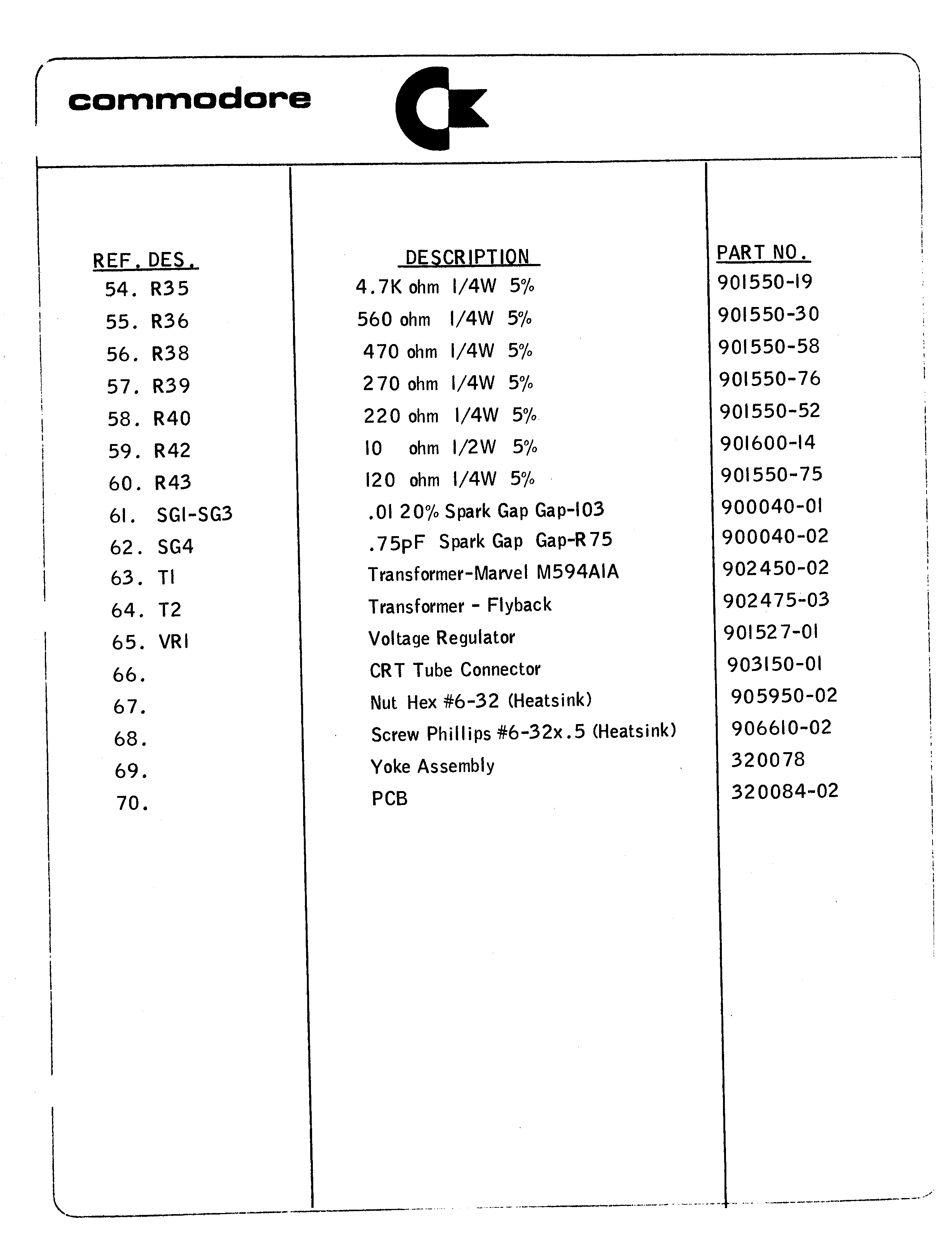
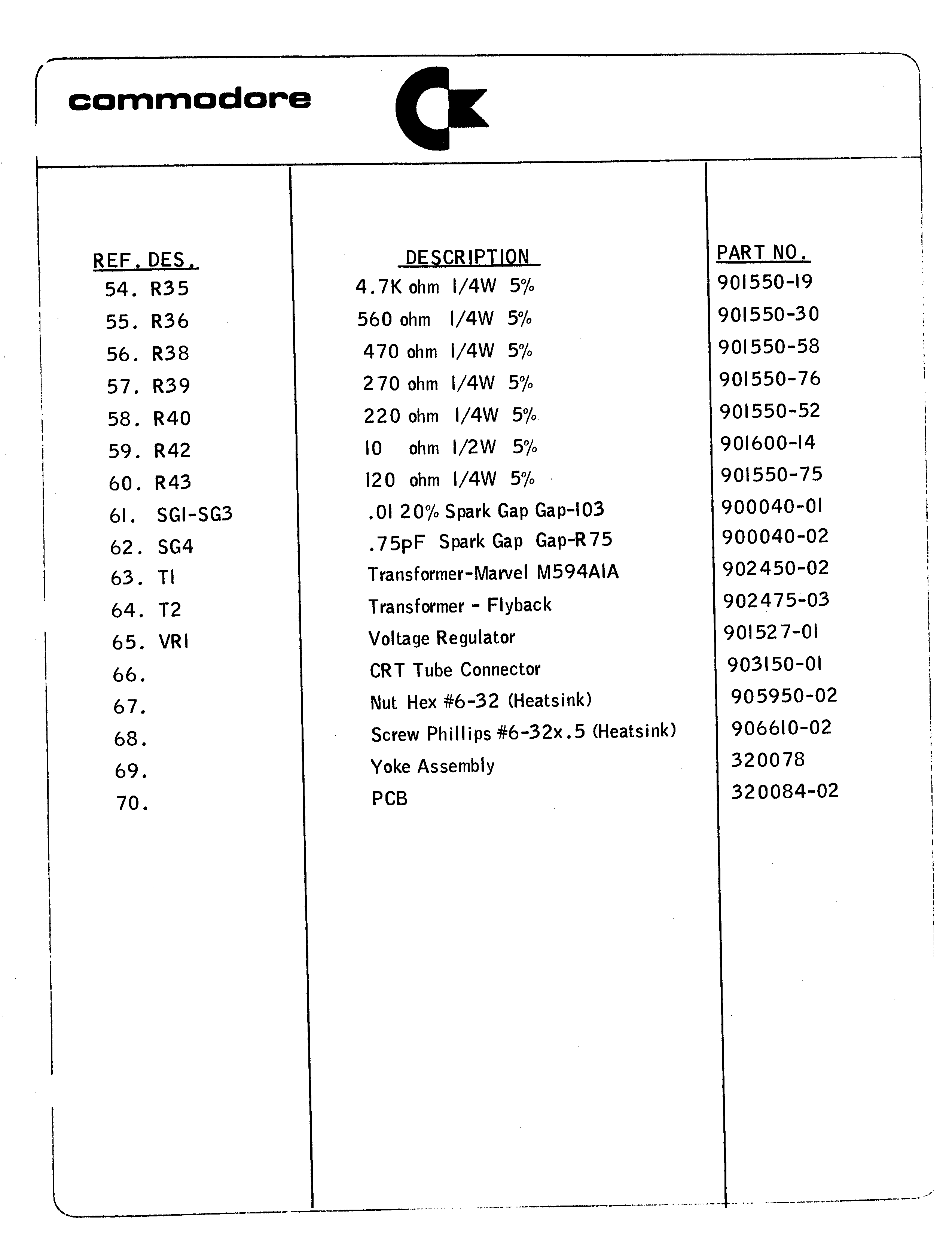
Sheet 3 of 3 of Commodore's Display Assembly Component Cross Reference for the Commodore PET 2001 display board: items 54 to 70, the remaining resistors, the four spark gaps, transformers T1 and T2, regulator VR1 (901527-01), the CRT socket, the yoke and the bare PCB. A 2,544 × 3,296 pixel scan. Described on Video Board Parts List (3 of 3).
Source
[edit | edit source]

zimmers.net Commodore archive, http://www.zimmers.net/anonftp/pub/cbm/schematics/computers/pet/2001/parts-6.gif (same file name and size, 89,037 bytes; checked 2026-10-01).
Author
[edit | edit source]

Commodore Business Machines, Inc.
Licence
[edit | edit source]

Copyright Commodore Business Machines. Not freely licensed. Hosted for preservation and repair reference.
File history
Click on a date/time to view the file as it appeared at that time.
| Date/Time | Thumbnail | Dimensions | User | Comment | |
|---|---|---|---|---|---|
| current | 15:37, 17 April 2025 | | 2,544 × 3,296 (87 KB) | Josh (talk | contribs) | File uploaded with MsUpload Category:Commodore_PET_2001_Schematics |
You cannot overwrite this file.
File usage
The following page uses this file:
