

Psion Series 3a
 | |
| Psion Series 3a | |
| Specifications | |
|---|---|
| Developer | Psion PLC |
| Manufacturer | Psion PLC |
| Type | Clamshell palmtop computer |
| Released | July 1993 (UK) |
| CPU | NEC V30H core at 7.68 MHz, inside Psion's ASIC9 |
| Memory | 1 MB or 2 MB ROM; 256 KB or 512 KB SRAM, later 1 MB or 2 MB pseudo-static RAM |
| Storage | Two internal Solid State Disk (SSD) slots |
| Display | 480 × 160 monochrome LCD with a grey plane |
| Sound | Loudspeaker and microphone; digital recording and playback |
| Dimensions | 165 mm × 85 mm × 22 mm |
| Weight | 275 g including batteries |
| OS / Firmware | EPOC16 (SIBO), with OPL |
| Predecessor | Psion Series 3 |
| Successor | Psion Series 3c |
| Model no. | Series 3a; Series 3aR (Russian); Acorn Pocket Book II |
The Psion Series 3a is a clamshell palmtop computer made by Psion PLC and launched in the UK in July 1993 as the successor to the Psion Series 3.[1] It runs twice as fast as the Series 3, has a screen with 67 % more area, a higher resolution and a grey plane, and adds a microphone for sound recording, while keeping the same case size, two AA cells and a quoted battery life of about 80 hours.[2][3] The processor, the two Series 3 support chips and a hardware real-time clock are combined in one Psion custom chip, ASIC9.[4]
History
The Series 3a was launched in the UK in July 1993 with 256 KB or 512 KB of RAM.[1][3] In 1995 Psion added 1 MB and 2 MB models and put more software into ROM, including a spell checker, thesaurus and communications software that had previously been sold separately.[2] From September 1995 the machine was built with a new TAB-bonded LCD module, and in November 1995 Psion made a set of changes to meet the EMC directives so that the machine could carry the CE mark.[1] The Psion Series 3c replaced it in 1996.[2]
Architecture and processor
ASIC9 is a 176-pin QFP standard-cell ASIC. It contains a V30HL processor core, the bus and LCD controllers, the CODEC serial interface, 16-bit timers, a watchdog, address and I/O protection, CPU clock generation and halting, the serial protocol controller, the real-time clock, power-supply control, the keyboard interface, and the 32.768 kHz and 7.68 MHz oscillators.[1] Every frequency in the machine comes from the 7.68 MHz crystal except the real-time clock, which runs from a 32.768 kHz watch crystal.[1]
The Series 3 used three chips: an NEC V30H processor, ASIC1 (the system controller) and ASIC2 (clock, keyboard, buzzer, SSD and power-supply interface). ASIC9 integrates all three.[4] The Series 3 was held to 3.84 MHz because ASIC1 read each 16-bit word from ROM as two 8-bit bytes; ASIC9 makes 16-bit accesses, so the same ROMs support 7.68 MHz.[4] ASIC9 also adds:[4]
- bank switching through four page registers (PSEL0–PSEL3), giving a 16 MB RAM space and a 16 MB ROM space beyond the V30H's 1 MB limit;
- a hardware 32-bit real-time clock counting at 1 Hz, so the 3a keeps time without the processor running (the Series 3 lost the time whenever the main batteries were out);
- a hardware wait that holds the processor while the SSD serial controller is busy;
- switch-on from the application buttons as well as the On key;
- a revised grey-scale scheme in which the second video map dims only pixels that are set.
Memory and storage
The main board holds the ROM (1 MB or 2 MB) and either 256 KB or 512 KB of static RAM, or 1 MB or 2 MB of pseudo-static RAM.[1] On a 256 KB board the two SRAMs sit inboard of the ROM with pads for two more beside them, next to the large ASIC9 package.[5] Soldering two 128K × 8 SRAMs (32-pin SOP, 100 ns or faster) into the empty pads takes a 256 KB machine to 512 KB; the original parts are Sony CXK581000M-12LB.[6] One owner who fitted Hitachi 628128 parts got a "Memory corruption" message and could not trace a soldering fault.[5]
Two Solid State Disk slots sit under the doors at each end of the base.[2] RAM SSDs have their own lithium cell and can be rewritten freely. Flash SSDs need no cell, but space taken by deleted or changed files is only recovered by reformatting the whole pack, so RAM packs suit data that changes often.[2] Writing and formatting Flash packs uses the +16 V Vh rail; reading them does not.[4]
Display
The screen is 480 × 160 pixels, up to 80 characters by 25 lines, on a retardation-film LCD with no backlight.[3] A grey plane gives one grey level between black and white. Series 3 software runs in a compatibility mode at the older machine's resolution.[2] Contrast is set in software: the LCD bias rail Vee1 is generated by a flyback converter whose output follows a DAC.[4]
Apart from the row and column drivers on the LCD module, all the active circuitry is on the main board. A small daughter board links the main board to the LCD module, the membrane keypad, the SSD slots and the speaker.[1] Two TAB LCD modules were used: a Seiko module with positive bias and a Hitachi module with negative bias. Main boards before revision 4.0 support only negative-bias modules; revision 4.0 and later boards are built for one or the other, and positive-bias boards have a "+" in their serial number. Psion's manual warns that a negative-bias module connected to a positive-bias board will be damaged.[1]
Sound
The 3a has a loudspeaker and a microphone for recording and playing back sound. Recordings are uncompressed and take 8,000 bytes per second.[3][2] The speaker also generates DTMF tones for dialling a telephone held against it.[3]
Input, output and expansion
The keyboard has 58 keys in a QWERTY layout, with eight touch-sensitive application buttons on a membrane above it.[3] The keyboard interface scans a matrix by driving each column high in turn and reading the rows.[4]
The expansion port is a 1.536 Mbit/s synchronous serial link, the same protocol as the SSD slots. Psion's 3-Link serial and parallel interfaces plug into it and contain their own ASIC to convert the protocol and levels; the 3-Link serial interface provides RS-232 at up to 19,200 bit/s.[1][3][7] Microswitches on the SSD doors and the expansion-port door raise an NMI when a pack or device is removed or fitted.[4]
Power
The Series 3a runs from two AA cells, about 80 hours of use with alkaline cells, with a lithium backup cell that holds the memory while the main cells are changed.[3] The backup cell is a CR1620 and sits under SSD door B.[2][1] The optional mains adaptor is rated 9–10 V at 150 mA.[3]
The power supply switches a set of rails under software control. The SIBO hardware reference describes them as follows.[4]
| Rail | Supplies | Notes |
|---|---|---|
| Vcc1 | ASIC9 and all the memory | Present in every state. Nominally 3.3 V on ASIC9 machines. Current-limited to a few hundred microamps in standby. Fed from the backup cell when the main cells are absent. |
| Vcc2 | The processor and anything that can be shut down; expansion port power | 5 V even in a 3.3 V system. Off in standby. |
| Vcc3 | The LCD module and its drivers | Software switched; 5 V or 3.3 V to match Vcc1 |
| Vcc5 | The 5 V pin of the SSD slots | Software switched |
| Vee1 | LCD bias (contrast) | Software switched negative rail from a flyback converter, set by a DAC |
| Vh | Flash SSD programming voltage | Software switched, +16 V from a flyback converter |
Psion's final-test limits for the Series 3a are 0.205 mA in standby and 27.0 mA on and idle for the 256 KB and 512 KB models, 0.245 mA and 32 mA for 1 MB, and 0.310 mA and 40 mA for 2 MB.[1] The Psion Series 3a Troubleshooting Guide explains how to use them.
Variants
The Series 3aR is a Russian-market version with Russian software in ROM.[2] Acorn sold the Series 3a as the Acorn Pocket Book II, with Agenda renamed Schedule and a Plotter application added.[2] Psion's spares lists include Pocket Book II main boards with 256 KB, 512 KB and 1 MB.[1]
Service manual and documentation
- File:Psion Series 3a Service Manual (June 1996).pdf – Psion's service manual: circuit description, fault table, exploded views with part numbers, disassembly and reassembly, the battery wire assembly and the factory final test with current limits.[1]
- File:Psion Series 3a User Guide (July 1993).pdf – the owner's manual, including resetting and the specification.[3]
- SIBO Hardware Reference – Psion's description of ASIC1, ASIC2, ASIC9 and the power supply rails.[4]
Known faults
The documented weak points of the Series 3 clamshell are broken hinges (there are four), a button bar that stops working, and deterioration of the cable between the keyboard half and the screen, which shows as vertical lines on the display.[2] The lead between the battery contacts and the main board flexes each time the lid is opened, and Psion recommended fitting new battery wires whenever a machine was dismantled.[1] These are covered in:
- Psion Series 3a Troubleshooting Guide
- Psion Series 3a General Maintenance
- Psion Series 3a Hinge Repair
Gallery
-
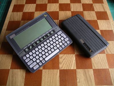 Psion Series 3a, closed
 -
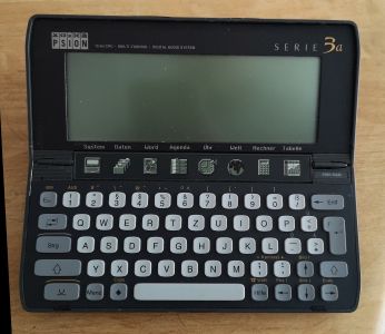 A German-market Series 3a (Serie 3a) with 256 KB, open

Related pages
- Psion Series 3a General Maintenance
- Psion Series 3a Troubleshooting Guide
- Psion Series 3a Hinge Repair
- Psion Series 3
- Psion Series 3c
- Psion Series 3mx
- Psion Siena
- Battery Refurbishment
References
- ↑ 1.00 1.01 1.02 1.03 1.04 1.05 1.06 1.07 1.08 1.09 1.10 1.11 1.12 1.13 Psion PLC, Series 3a Service Manual, Version 1.0, June 1996, part no. 6103-0114-01. Hosted on this wiki as File:Psion Series 3a Service Manual (June 1996).pdf. Introduction (p. 1), circuit description (pp. 2–3), troubleshooting guide (p. 4), exploded views and EMC modifications (pp. 5–7), spares kits (pp. 7–8), disassembly (pp. 9–13), reassembly notes (pp. 13–16) and final test procedure (pp. 16–23).
- ↑ 2.00 2.01 2.02 2.03 2.04 2.05 2.06 2.07 2.08 2.09 2.10 "Psion Series 3", Wikipedia. Model history, screen comparison, the 1995 revision, the Series 3aR and Acorn Pocket Book II, SSD types, the CR1620 backup cell and the documented hinge, button-bar and screen-cable problems.
- ↑ 3.00 3.01 3.02 3.03 3.04 3.05 3.06 3.07 3.08 3.09 Psion PLC, Series 3a User Guide, v1.0, July 1993, part no. 6103-0044-01. Hosted on this wiki as File:Psion Series 3a User Guide (July 1993).pdf. "Specification" and "Resetting the Series 3a".
- ↑ 4.00 4.01 4.02 4.03 4.04 4.05 4.06 4.07 4.08 4.09 4.10 Psion PLC, SIBO Hardware Reference, version 2.10, 3 February 1995, in the Psion Documentation Project. Sections "The Principal Chip Set", "ASIC9" and "PSU subsystem".
- ↑ 5.0 5.1 David Kimberlin-Wyer, "Psion Series 3a Memory Upgrade", primrosebank.net. Disassembly steps 1–19, the board layout and the failed upgrade with Hitachi 628128 parts.
- ↑ Nils (unix-ag.org), "S3a 512kB upgrade". SRAM types and the disassembly sequence.
- ↑ "Psion specifications", netogram.com. Series 3a serial speed and keyboard.