

Macintosh Classic II Capacitor Replacement Guide: Difference between revisions
Verification drive: flag unverified component data pending check against a primary source |
Verification drive: SAFETY FIX - the single analogue-board table mixed the 120V and 240V board variants. It listed CP1 AND CP13 at 220uF 250V (the 120V voltage-doubler pair) alongside CL1/CL11/CV2, which are 240V-board parts. On a 240V board CP1 is 220uF 400V and CP13 is a jumper with no capacitor; 240V mains rectifies to ~340V DC, so a 250V part there fails violently. Split into separate 120V and 240V tables per console5 630-0560, cross-checked against Recap-a-Mac 240V photo guide. Added con... |
||
| Line 1: | Line 1: | ||
{{ | The '''Macintosh Classic II''' is one of the machines that must be recapped. Its logic board uses surface-mount electrolytics that leak a conductive, corrosive electrolyte, and it also carries a 1/2 AA lithium cell of the type that has a reputation for venting over the board. Recap-a-Mac's advice for an untouched example is blunt: if you do not know whether the battery has been changed or the capacitors replaced, see to it right away.<ref name="recapcii" /> | ||
''' | |||
The Classic and the Classic II share a power/sweep board but '''not''' a logic board, so the two halves of this guide have different scopes. | |||
== Safety == | |||
{{Warning|'''The CRT anode holds charge after power-off.''' Discharge it before working on the power/sweep board, the anode lead or the CRT socket board — see [[CRT Discharge Procedure]]. | |||
'''The power/sweep board is a mains-connected switch-mode supply.''' CP1 (and, on 110 V boards, CP13) is the primary reservoir, sitting at rectified mains potential and holding charge after the machine is unplugged. Measure across it before touching the primary side. Recapping this board is a normal repair — measure first, and read the next warning about its voltage rating. | |||
'''The lithium battery can explode if mishandled.''' That is Apple's own wording.<ref name="APPLESS" /> | |||
Apple's US Service Source rates the machine at 100–120 V AC, 47–63 Hz, 100 W maximum; 220 V power/sweep boards were also produced and have their own part numbers.<ref name="APPLESS" />}} | |||
== Do the Battery First == | |||
Apple's verification procedure is to remove the logic board, measure across the cell, and '''replace it if it reads below 3.0 V'''.<ref name="APPLESS" /> The Apple part number for the cell is 742-0011.<ref name="APPLESS" /> | |||
Recap-a-Mac notes that the particular brand of 1/2 AA cell Apple used in this family has a tendency to spray electrolyte across the logic board, in some cases doing damage that cannot be repaired.<ref name="recapclassic" /> Remove it before you do anything else. See [[Battery Explosion, Capacitor or Corrosion Damage]]. | |||
== Capacitor Inspection == | == Capacitor Inspection == | ||
Surface-mount electrolytics rarely bulge. Look instead for: | |||
* Dark haloes or dried crust at the base of the cans. | |||
* Dull or green solder joints on nearby IC pins. | |||
* Thinned or missing traces, best seen under a loupe with light raking across the board. | |||
See [[Capacitor Failure Symptoms]]. | |||
== | == Logic Board == | ||
Two variants exist, and they are easy to tell apart without a part number: the earlier board has '''four ROM chips''' in the bottom right corner and '''13''' surface-mount electrolytics; the later one has '''two ROM chips''' and '''17'''.<ref name="recapcii" /> | |||
<templatestyles src="Template:StyledTable/styles.css" /> | <templatestyles src="Template:StyledTable/styles.css" /> | ||
{| class="wikitable styled-table" style="width: | {| class="wikitable styled-table" style="width:70%; text-align:center;" | ||
|+ ''' | |+ '''Classic II logic board (630-0055-B / 820-0326-B or 630-0401-B / 820-0401-B)''' | ||
|- | |||
! Reference !! Capacitance !! Voltage !! Fitted on | |||
|- | |||
| C3 || 47 µF || 16 V || Both | |||
|- | |||
| C4 || 47 µF || 16 V || Both | |||
|- | |||
| C5 || 10 µF || 16 V || Both | |||
|- | |||
| C6 || 10 µF || 16 V || Both | |||
|- | |||
| C7 || 10 µF || 16 V || Both | |||
|- | |||
| C8 || 10 µF || 16 V || Both | |||
|- | |||
| C9 || 1 µF || 50 V || Both | |||
|- | |||
| C10 || 10 µF || 16 V || Both | |||
|- | |||
| C11 || 10 µF || 16 V || Both | |||
|- | |||
| C12 || 10 µF || 16 V || Both | |||
|- | |||
| C13 || 47 µF || 16 V || Both | |||
|- | |||
| C14 || 10 µF || 16 V || Both | |||
|- | |||
| C15 || 1 µF || 50 V || Both | |||
|- | |||
| C21 || 10 µF || 16 V || 630-0055 only | |||
|- | |||
| C74 || 10 µF || 16 V || 630-0055 only | |||
|- | |||
| C79 || 10 µF || 16 V || 630-0055 only | |||
|- | |||
| C106 || 10 µF || 16 V || 630-0055 only | |||
|} | |||
Two independent sources agree on the totals. Console5 gives the designators above and flags the last four as fitted to board 630-0055 only;<ref name="c5cii" /> Recap-a-Mac's photographic guides, made from physical boards, count '''8 × 10 µF 16 V, 3 × 47 µF 16 V and 2 × 1 µF 50 V''' on the 13-capacitor board and '''12 × 10 µF 16 V, 3 × 47 µF 16 V and 2 × 1 µF 50 V''' on the 17-capacitor board.<ref name="recapciia" /><ref name="recapciib" /> Those tallies match exactly. Count the capacitors on your own board before ordering. | |||
<gallery mode="packed" heights="250"> | |||
File:Classic II (A) recapping.jpg|Classic II 13-capacitor logic board | |||
File:Classic II (B) Recapping.jpg|Classic II 17-capacitor logic board | |||
</gallery> | |||
== Power/Sweep Board == | |||
The Classic and Classic II share this board.<ref name="recapanalog" /> Apple lists '''four''' field-replaceable variants:<ref name="APPLESS" /> | |||
* 661-0597 — 110 V, Rev. A | |||
* 661-0599 — 220 V, Rev. A | |||
* 661-0651 — 110 V, Rev. B | |||
* 661-0652 — 220 V, Rev. B | |||
The bare boards carry their own numbers: 630-0395, 630-0420, 630-0525 and 630-0560.<ref name="c5395" /><ref name="c5560" /> | |||
{{Warning|'''CP1 is rated differently on 110 V and 220–240 V boards, and this matters.''' | |||
On a '''110/120 V''' board the mains input is a voltage doubler, and CP1 and CP13 are a '''series pair of 220 µF 250 V''' capacitors. | |||
On a '''220–240 V''' board there is no doubler. '''CP1 is a single 220 µF 400 V capacitor and CP13 is a jumper with no capacitor fitted at all.'''<ref name="c5560" /> Recap-a-Mac's photographic guide for a 240 V board independently shows one 220 µF 400 V part and no 250 V electrolytic anywhere on the board.<ref name="recapanalog" /> | |||
240 V mains rectifies to roughly 340 V DC. Fitting a 250 V capacitor at CP1 on a 240 V board puts it far over its rating, and it will fail — loudly, and possibly violently. Identify which board you have before you order parts.}} | |||
=== 110/120 V board (630-0560, 120 V list; also 630-0395) === | |||
{| class="wikitable styled-table" style="width:80%; text-align:center;" | |||
|+ '''Classic / Classic II power/sweep board — 120 V version''' | |||
|- | |- | ||
! | ! Reference !! Capacitance !! Voltage | ||
|- | |- | ||
| | | CF1 || 47 µF || 25 V | ||
|- | |- | ||
| | | CF2 || 220 µF || 16 V | ||
|- | |- | ||
| | | CF3 || 1000 µF || 16 V | ||
|- | |- | ||
| | | CF4 || 470 µF || 25 V | ||
|- | |- | ||
| | | CL1 || 10 µF || 50 V | ||
|- | |- | ||
| | | CL2 || 4.7 µF || 250 V | ||
|- | |- | ||
| | | CL3 || 1 µF || 50 V | ||
|- | |- | ||
| | | CP1 || 220 µF || 250 V | ||
|- | |- | ||
| | | CP2 || 470 µF || 50 V | ||
|- | |- | ||
| | | CP3 || 10 µF || 25 V | ||
|- | |- | ||
| | | CP4 || 47 µF || 25 V | ||
|- | |- | ||
| | | CP5 || 1 µF || 50 V | ||
|- | |- | ||
| | | CP6 || 2200 µF || 10 V | ||
|- | |- | ||
| | | CP7 || 1000 µF || 10 V | ||
|- | |- | ||
| | | CP8 || 2200 µF || 16 V | ||
|- | |- | ||
| | | CP9 || 470 µF || 25 V | ||
|- | |- | ||
| | | CP10 || 470 µF || 25 V | ||
|- | |- | ||
| | | CP11 || 220 µF || 50 V | ||
|- | |- | ||
| | | CP12 || 1000 µF || 16 V | ||
|- | |- | ||
| | | CP13 || 220 µF || 250 V | ||
|- | |- | ||
| | | CP31 || 1000 µF || 6.3 V | ||
|- | |- | ||
| | | CP34 || 1 µF || 50 V | ||
|- | |- | ||
| | | CP35 || 1 µF || 50 V | ||
|- | |- | ||
| | | CP36 || 2200 µF || 10 V | ||
|- | |- | ||
| | | CP37 || 1 µF || 50 V | ||
|} | |} | ||
' | From Console5's list for 630-0560.<ref name="c5560" /> Console5's list for the earlier 630-0395 differs in two places: CP2 is 1000 µF 35 V and CP11 is 220 µF 25 V on that board.<ref name="c5395" /> | ||
=== | === 220/240 V board (630-0560, 240 V list; also 630-0420, 630-0525) === | ||
{| class="wikitable styled-table" style="width:80%; text-align:center;" | |||
{| class="wikitable styled-table" style="width: | |+ '''Classic / Classic II power/sweep board — 240 V version''' | ||
|+ ''' | |- | ||
! Reference !! Capacitance !! Voltage | |||
|- | |||
| CF1 || 47 µF || 25 V | |||
|- | |||
| CF2 || 220 µF || 16 V | |||
|- | |||
| CF3 || 1000 µF || 16 V | |||
|- | |||
| CF4 || 470 µF || 25 V | |||
|- | |||
| CL1 || 1000 µF || 25 V | |||
|- | |||
| CL2 || 4.7 µF || 250 V | |||
|- | |||
| CL3 || 1 µF || 50 V | |||
|- | |||
| CL11 || 47 µF || 16 V | |||
|- | |||
| CP1 || 220 µF || '''400 V''' | |||
|- | |||
| CP2 || 470 µF || 50 V | |||
|- | |||
| CP3 || 10 µF || 25 V | |||
|- | |||
| CP4 || 47 µF || 25 V | |||
|- | |||
| CP5 || 1 µF || 50 V | |||
|- | |||
| CP6 || 2200 µF || 10 V | |||
|- | |||
| CP7 || 1000 µF || 10 V | |||
|- | |||
| CP8 || 2200 µF || 16 V | |||
|- | |||
| CP9 || 470 µF || 25 V | |||
|- | |- | ||
| CP10 || 470 µF || 25 V | |||
|- | |- | ||
| | | CP11 || 220 µF || 50 V | ||
|- | |- | ||
| | | CP12 || 1000 µF || 16 V | ||
|- | |- | ||
| | | CP13 || colspan="2" | '''Jumper — no capacitor fitted''' | ||
|- | |- | ||
| CP34 || 1 µF || 50 V | |||
|- | |- | ||
| | | CP36 || 2200 µF || 10 V | ||
|- | |- | ||
| | | CP37 || 1 µF || 50 V | ||
|- | |- | ||
| | | CV2 || 470 µF || 10 V | ||
|} | |} | ||
Console5 publishes this as the 240 V list for 630-0560, and the same list without the CP13 note as 630-0525.<ref name="c5560" /><ref name="c5525" /> Recap-a-Mac's photographic guide for a 240 V board agrees on every value and quantity except the 1 µF 50 V positions, where it marks two where Console5 lists four (CL3, CP5, CP34, CP37).<ref name="recapanalog" /> Check your own board. | |||
< | |||
</ | |||
[[File:Mac_classic_analog_recap.jpg|thumb|694x694px|Macintosh Classic / Classic II power/sweep board recapping guide (240 V version)|center]] | |||
Recap-a-Mac also warns that an earlier revision of this board exists with a slightly different neck-board connector and one or two capacitors different from the guide above, and that besides capacitors these boards suffer cracked solder joints, corrosion and short circuits from leakage, and failure of the DIP ICs '''IF1''', '''QP1''' and '''JP1'''.<ref name="recapanalog" /> | |||
=== Voltage adjustment === | |||
Apple's Service Source for the Classic and Classic II contains Video and Yoke adjustment procedures and no voltage adjustment, and publishes no rail tolerances for the machine.<ref name="APPLESS" /> Recap-a-Mac reports that the output voltage can be adjusted using the variable resistor '''PP1''' on the power/sweep board.<ref name="recapanalog" /> | |||
== Replacement Capacitors == | |||
For the logic board, Recap-a-Mac uses solid tantalum at the same values:<ref name="recapclassic" /> | |||
* 1 µF 50 V — KEMET T491B105K050AT | |||
* 47 µF 16 V — KEMET T491D476K016AT | |||
Why that class of part: | |||
* '''Solid tantalum''' has no liquid electrolyte and cannot leak. It fails '''short''', so derate generously — a part rated well above the rail it sits on is far less likely to be driven into failure by a switch-on surge. | |||
* '''Solid polymer aluminium''' also has no liquid electrolyte and typically fails '''open''' rather than short, which is gentler on whatever is downstream, and has lower ESR. It is the safer failure mode for vintage hardware. | |||
* '''Ordinary aluminium electrolytic''' matches the original footprint exactly and is the cheapest option, but it will eventually leak again. | |||
On the logic board, check the physical footprint before ordering. Space around several of the 10 µF positions is tight and a wider can will sit over its own pads, making it impossible to solder properly. There is also exposed plastic at the bottom edge of the board next to a cluster of capacitors, which is very easy to melt with a soldering iron.<ref name="recapccii" /> | |||
For the power/sweep board use 105 °C-rated aluminium electrolytics from a known manufacturer throughout, and match or exceed the rating printed on the part you removed. | |||
== Capacitor Replacement Procedure == | |||
# '''Remove the logic board''' and take the battery off it. | |||
# '''Discharge the CRT''' before touching the power/sweep board — see [[CRT Discharge Procedure]]. | |||
# '''Confirm CP1 has discharged''' before working on the primary side. | |||
# '''Remove the surface-mount capacitors''' by alternating heat between the terminals while tilting the can gently, or with hot air and the plastic shielded. Twisting a can off cold takes the pads with it. | |||
# '''Clean thoroughly''' with 99 % isopropyl alcohol and a soft brush until a clean swab comes away clean. | |||
# '''Inspect and test''' continuity across every trace that ran under or beside a capacitor, and repair breaks before fitting anything new. | |||
# '''Fit the new parts''' the right way round. On a tantalum the stripe marks '''positive'''; on an aluminium electrolytic it marks '''negative'''. | |||
# '''Check for shorts''' across each rail before applying power. | |||
Tools are listed on [[Recommended Tools]]. | |||
== | == Module Part Numbers == | ||
From Apple's exploded view for the Classic, Classic II and Performa 200:<ref name="APPLESS" /> | |||
* Logic board — 661-0596 (1 MB, Classic) or '''661-0672''' (2 MB, Classic II and Performa 200) | |||
* | * Power/sweep board — 661-0597, 661-0599, 661-0651 or 661-0652 as listed above | ||
* Lithium battery — 742-0011 | |||
* Power | * CRT and yoke assembly — 076-0546 | ||
* | * Floppy drive — 661-0474 | ||
* | |||
== Related Pages == | == Related Pages == | ||
* [[Macintosh | * [[Macintosh Classic II]] | ||
* [[Macintosh | * [[Macintosh Classic / Classic II General Maintenance]] | ||
* [[Macintosh Floppy Drive Maintenance]] | * [[Macintosh Classic / Classic II Troubleshooting]] | ||
* [[Battery Explosion, Capacitor or Corrosion Damage]] | |||
* [[Capacitor Failure Symptoms]] | |||
* [[Macintosh Floppy Drive Maintenance]] | |||
* [[CRT Discharge Procedure]] | * [[CRT Discharge Procedure]] | ||
* [[Recommended Tools]] | |||
<references/> | == References == | ||
<references> | |||
<ref name="APPLESS">Apple Computer, ''Macintosh Classic / Classic II / Performa 200 Service Source'', hosted here as [[:File:Macintosh Classic - Classic II.pdf]]. Specifications (Electrical), Additional Procedures — Battery Verification (3.0 V threshold and the explosion warning), Adjustments (Video and Yoke only), and the Exploded View parts list. Apple's Service Source is module-level: procedures, thresholds and field-replaceable-unit numbers, not component values.</ref> | |||
<ref name="c5cii">Console5 TechWiki, "Macintosh Classic II" — logic board 630-0055-B / 820-0326-B or 630-0401-B / 820-0401-B. https://wiki.console5.com/wiki/Macintosh_Classic_II Secondary source — a vendor cap-kit list, not Apple documentation.</ref> | |||
<ref name="c5395">Console5 TechWiki, "Mac Analog Board: 630-0395". https://wiki.console5.com/wiki/Mac_Analog_Board:_630-0395 Secondary source.</ref> | |||
<ref name="c5525">Console5 TechWiki, "Mac Analog Board: 630-0525". https://wiki.console5.com/wiki/Mac_Analog_Board:_630-0525 Secondary source.</ref> | |||
<ref name="c5560">Console5 TechWiki, "Mac Analog Board: 630-0560", which publishes separate 120 V and 240 V lists including CP1 at 250 V versus 400 V and CP13 as a jumper on the 240 V board. https://wiki.console5.com/wiki/Mac_Analog_Board:_630-0560 Secondary source.</ref> | |||
<ref name="recapcii">Bruce / Recap-a-Mac, "Macintosh Classic II (Rev A)". https://recapamac.com.au/macintosh-classic-ii-a/ The 13-capacitor / four-ROM versus 17-capacitor / two-ROM distinction. Secondary source.</ref> | |||
<ref name="recapciia">Bruce / Recap-a-Mac, "Macintosh Classic II (Rev A)" recapping guide — 8 × 10 µF 16 V, 3 × 47 µF 16 V, 2 × 1 µF 50 V. https://recapamac.com.au/macintosh-classic-ii-a/ Secondary source, values photographed from a physical board.</ref> | |||
<ref name="recapciib">Bruce / Recap-a-Mac, "Macintosh Classic II (Rev B)" recapping guide — 12 × 10 µF 16 V, 3 × 47 µF 16 V, 2 × 1 µF 50 V. https://recapamac.com.au/macintosh-classic-ii-b/ Secondary source.</ref> | |||
<ref name="recapanalog">Bruce / Recap-a-Mac, "Macintosh Classic I + II Analog Board (220V – 240V version)". https://recapamac.com.au/macintosh-classic-analog/ Capacitor values and quantities for the 240 V board including the single 220 µF 400 V part, the PP1 voltage adjustment, the IF1 / QP1 / JP1 DIP IC failures, and the warning about an earlier board revision. Secondary source.</ref> | |||
<ref name="recapclassic">Bruce / Recap-a-Mac, "Macintosh Classic". https://recapamac.com.au/macintosh-classic/ The 1/2 AA battery failure mode in this family, and the KEMET tantalum part numbers. Secondary source.</ref> | |||
<ref name="recapccii">Bruce / Recap-a-Mac, "Macintosh Colo(u)r Classic II". https://recapamac.com.au/macintosh-colour-classic-ii/ The warning about melting the exposed plastic at the bottom edge of the board while soldering. Secondary source.</ref> | |||
</references> | |||
[[Category:Apple Vintage Computers]] | [[Category:Apple Vintage Computers]] | ||
[[Category:Capacitor Replacement Guides]] | [[Category:Capacitor Replacement Guides]] | ||
Latest revision as of 00:19, 23 September 2026
The Macintosh Classic II is one of the machines that must be recapped. Its logic board uses surface-mount electrolytics that leak a conductive, corrosive electrolyte, and it also carries a 1/2 AA lithium cell of the type that has a reputation for venting over the board. Recap-a-Mac's advice for an untouched example is blunt: if you do not know whether the battery has been changed or the capacitors replaced, see to it right away.[1]
The Classic and the Classic II share a power/sweep board but not a logic board, so the two halves of this guide have different scopes.
Safety
[edit | edit source] | The CRT anode holds charge after power-off. Discharge it before working on the power/sweep board, the anode lead or the CRT socket board — see CRT Discharge Procedure.
The power/sweep board is a mains-connected switch-mode supply. CP1 (and, on 110 V boards, CP13) is the primary reservoir, sitting at rectified mains potential and holding charge after the machine is unplugged. Measure across it before touching the primary side. Recapping this board is a normal repair — measure first, and read the next warning about its voltage rating. The lithium battery can explode if mishandled. That is Apple's own wording.[2] Apple's US Service Source rates the machine at 100–120 V AC, 47–63 Hz, 100 W maximum; 220 V power/sweep boards were also produced and have their own part numbers.[2] |
Do the Battery First
[edit | edit source]Apple's verification procedure is to remove the logic board, measure across the cell, and replace it if it reads below 3.0 V.[2] The Apple part number for the cell is 742-0011.[2]
Recap-a-Mac notes that the particular brand of 1/2 AA cell Apple used in this family has a tendency to spray electrolyte across the logic board, in some cases doing damage that cannot be repaired.[3] Remove it before you do anything else. See Battery Explosion, Capacitor or Corrosion Damage.
Capacitor Inspection
[edit | edit source]Surface-mount electrolytics rarely bulge. Look instead for:
- Dark haloes or dried crust at the base of the cans.
- Dull or green solder joints on nearby IC pins.
- Thinned or missing traces, best seen under a loupe with light raking across the board.
See Capacitor Failure Symptoms.
Logic Board
[edit | edit source]Two variants exist, and they are easy to tell apart without a part number: the earlier board has four ROM chips in the bottom right corner and 13 surface-mount electrolytics; the later one has two ROM chips and 17.[1]
| Reference | Capacitance | Voltage | Fitted on |
|---|---|---|---|
| C3 | 47 µF | 16 V | Both |
| C4 | 47 µF | 16 V | Both |
| C5 | 10 µF | 16 V | Both |
| C6 | 10 µF | 16 V | Both |
| C7 | 10 µF | 16 V | Both |
| C8 | 10 µF | 16 V | Both |
| C9 | 1 µF | 50 V | Both |
| C10 | 10 µF | 16 V | Both |
| C11 | 10 µF | 16 V | Both |
| C12 | 10 µF | 16 V | Both |
| C13 | 47 µF | 16 V | Both |
| C14 | 10 µF | 16 V | Both |
| C15 | 1 µF | 50 V | Both |
| C21 | 10 µF | 16 V | 630-0055 only |
| C74 | 10 µF | 16 V | 630-0055 only |
| C79 | 10 µF | 16 V | 630-0055 only |
| C106 | 10 µF | 16 V | 630-0055 only |
Two independent sources agree on the totals. Console5 gives the designators above and flags the last four as fitted to board 630-0055 only;[4] Recap-a-Mac's photographic guides, made from physical boards, count 8 × 10 µF 16 V, 3 × 47 µF 16 V and 2 × 1 µF 50 V on the 13-capacitor board and 12 × 10 µF 16 V, 3 × 47 µF 16 V and 2 × 1 µF 50 V on the 17-capacitor board.[5][6] Those tallies match exactly. Count the capacitors on your own board before ordering.
-
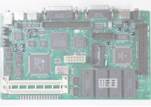 Classic II 13-capacitor logic board
 -
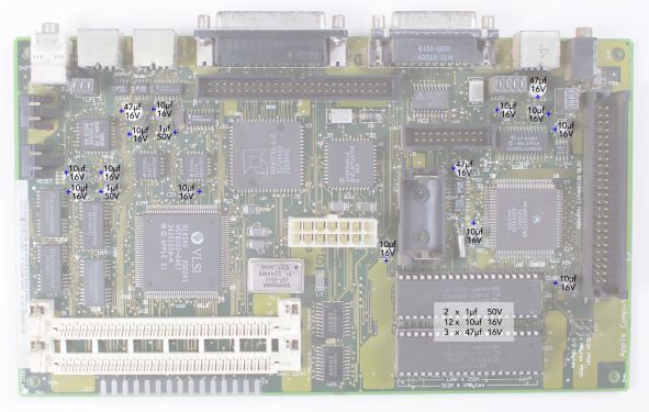 Classic II 17-capacitor logic board
_recapping.jpg)
_Recapping.jpg)
Power/Sweep Board
[edit | edit source]The Classic and Classic II share this board.[7] Apple lists four field-replaceable variants:[2]
- 661-0597 — 110 V, Rev. A
- 661-0599 — 220 V, Rev. A
- 661-0651 — 110 V, Rev. B
- 661-0652 — 220 V, Rev. B
The bare boards carry their own numbers: 630-0395, 630-0420, 630-0525 and 630-0560.[8][9]
| CP1 is rated differently on 110 V and 220–240 V boards, and this matters.
On a 110/120 V board the mains input is a voltage doubler, and CP1 and CP13 are a series pair of 220 µF 250 V capacitors. On a 220–240 V board there is no doubler. CP1 is a single 220 µF 400 V capacitor and CP13 is a jumper with no capacitor fitted at all.[9] Recap-a-Mac's photographic guide for a 240 V board independently shows one 220 µF 400 V part and no 250 V electrolytic anywhere on the board.[7] 240 V mains rectifies to roughly 340 V DC. Fitting a 250 V capacitor at CP1 on a 240 V board puts it far over its rating, and it will fail — loudly, and possibly violently. Identify which board you have before you order parts. |
110/120 V board (630-0560, 120 V list; also 630-0395)
[edit | edit source]| Reference | Capacitance | Voltage |
|---|---|---|
| CF1 | 47 µF | 25 V |
| CF2 | 220 µF | 16 V |
| CF3 | 1000 µF | 16 V |
| CF4 | 470 µF | 25 V |
| CL1 | 10 µF | 50 V |
| CL2 | 4.7 µF | 250 V |
| CL3 | 1 µF | 50 V |
| CP1 | 220 µF | 250 V |
| CP2 | 470 µF | 50 V |
| CP3 | 10 µF | 25 V |
| CP4 | 47 µF | 25 V |
| CP5 | 1 µF | 50 V |
| CP6 | 2200 µF | 10 V |
| CP7 | 1000 µF | 10 V |
| CP8 | 2200 µF | 16 V |
| CP9 | 470 µF | 25 V |
| CP10 | 470 µF | 25 V |
| CP11 | 220 µF | 50 V |
| CP12 | 1000 µF | 16 V |
| CP13 | 220 µF | 250 V |
| CP31 | 1000 µF | 6.3 V |
| CP34 | 1 µF | 50 V |
| CP35 | 1 µF | 50 V |
| CP36 | 2200 µF | 10 V |
| CP37 | 1 µF | 50 V |
From Console5's list for 630-0560.[9] Console5's list for the earlier 630-0395 differs in two places: CP2 is 1000 µF 35 V and CP11 is 220 µF 25 V on that board.[8]
220/240 V board (630-0560, 240 V list; also 630-0420, 630-0525)
[edit | edit source]| Reference | Capacitance | Voltage |
|---|---|---|
| CF1 | 47 µF | 25 V |
| CF2 | 220 µF | 16 V |
| CF3 | 1000 µF | 16 V |
| CF4 | 470 µF | 25 V |
| CL1 | 1000 µF | 25 V |
| CL2 | 4.7 µF | 250 V |
| CL3 | 1 µF | 50 V |
| CL11 | 47 µF | 16 V |
| CP1 | 220 µF | 400 V |
| CP2 | 470 µF | 50 V |
| CP3 | 10 µF | 25 V |
| CP4 | 47 µF | 25 V |
| CP5 | 1 µF | 50 V |
| CP6 | 2200 µF | 10 V |
| CP7 | 1000 µF | 10 V |
| CP8 | 2200 µF | 16 V |
| CP9 | 470 µF | 25 V |
| CP10 | 470 µF | 25 V |
| CP11 | 220 µF | 50 V |
| CP12 | 1000 µF | 16 V |
| CP13 | Jumper — no capacitor fitted | |
| CP34 | 1 µF | 50 V |
| CP36 | 2200 µF | 10 V |
| CP37 | 1 µF | 50 V |
| CV2 | 470 µF | 10 V |
Console5 publishes this as the 240 V list for 630-0560, and the same list without the CP13 note as 630-0525.[9][10] Recap-a-Mac's photographic guide for a 240 V board agrees on every value and quantity except the 1 µF 50 V positions, where it marks two where Console5 lists four (CL3, CP5, CP34, CP37).[7] Check your own board.

Recap-a-Mac also warns that an earlier revision of this board exists with a slightly different neck-board connector and one or two capacitors different from the guide above, and that besides capacitors these boards suffer cracked solder joints, corrosion and short circuits from leakage, and failure of the DIP ICs IF1, QP1 and JP1.[7]
Voltage adjustment
[edit | edit source]Apple's Service Source for the Classic and Classic II contains Video and Yoke adjustment procedures and no voltage adjustment, and publishes no rail tolerances for the machine.[2] Recap-a-Mac reports that the output voltage can be adjusted using the variable resistor PP1 on the power/sweep board.[7]
Replacement Capacitors
[edit | edit source]For the logic board, Recap-a-Mac uses solid tantalum at the same values:[3]
- 1 µF 50 V — KEMET T491B105K050AT
- 47 µF 16 V — KEMET T491D476K016AT
Why that class of part:
- Solid tantalum has no liquid electrolyte and cannot leak. It fails short, so derate generously — a part rated well above the rail it sits on is far less likely to be driven into failure by a switch-on surge.
- Solid polymer aluminium also has no liquid electrolyte and typically fails open rather than short, which is gentler on whatever is downstream, and has lower ESR. It is the safer failure mode for vintage hardware.
- Ordinary aluminium electrolytic matches the original footprint exactly and is the cheapest option, but it will eventually leak again.
On the logic board, check the physical footprint before ordering. Space around several of the 10 µF positions is tight and a wider can will sit over its own pads, making it impossible to solder properly. There is also exposed plastic at the bottom edge of the board next to a cluster of capacitors, which is very easy to melt with a soldering iron.[11]
For the power/sweep board use 105 °C-rated aluminium electrolytics from a known manufacturer throughout, and match or exceed the rating printed on the part you removed.
Capacitor Replacement Procedure
[edit | edit source]- Remove the logic board and take the battery off it.
- Discharge the CRT before touching the power/sweep board — see CRT Discharge Procedure.
- Confirm CP1 has discharged before working on the primary side.
- Remove the surface-mount capacitors by alternating heat between the terminals while tilting the can gently, or with hot air and the plastic shielded. Twisting a can off cold takes the pads with it.
- Clean thoroughly with 99 % isopropyl alcohol and a soft brush until a clean swab comes away clean.
- Inspect and test continuity across every trace that ran under or beside a capacitor, and repair breaks before fitting anything new.
- Fit the new parts the right way round. On a tantalum the stripe marks positive; on an aluminium electrolytic it marks negative.
- Check for shorts across each rail before applying power.
Tools are listed on Recommended Tools.
Module Part Numbers
[edit | edit source]From Apple's exploded view for the Classic, Classic II and Performa 200:[2]
- Logic board — 661-0596 (1 MB, Classic) or 661-0672 (2 MB, Classic II and Performa 200)
- Power/sweep board — 661-0597, 661-0599, 661-0651 or 661-0652 as listed above
- Lithium battery — 742-0011
- CRT and yoke assembly — 076-0546
- Floppy drive — 661-0474
Related Pages
[edit | edit source]- Macintosh Classic II
- Macintosh Classic / Classic II General Maintenance
- Macintosh Classic / Classic II Troubleshooting
- Battery Explosion, Capacitor or Corrosion Damage
- Capacitor Failure Symptoms
- Macintosh Floppy Drive Maintenance
- CRT Discharge Procedure
- Recommended Tools
References
[edit | edit source]- ↑ 1.0 1.1 Bruce / Recap-a-Mac, "Macintosh Classic II (Rev A)". https://recapamac.com.au/macintosh-classic-ii-a/ The 13-capacitor / four-ROM versus 17-capacitor / two-ROM distinction. Secondary source.
- ↑ 2.0 2.1 2.2 2.3 2.4 2.5 2.6 Apple Computer, Macintosh Classic / Classic II / Performa 200 Service Source, hosted here as File:Macintosh Classic - Classic II.pdf. Specifications (Electrical), Additional Procedures — Battery Verification (3.0 V threshold and the explosion warning), Adjustments (Video and Yoke only), and the Exploded View parts list. Apple's Service Source is module-level: procedures, thresholds and field-replaceable-unit numbers, not component values.
- ↑ 3.0 3.1 Bruce / Recap-a-Mac, "Macintosh Classic". https://recapamac.com.au/macintosh-classic/ The 1/2 AA battery failure mode in this family, and the KEMET tantalum part numbers. Secondary source.
- ↑ Console5 TechWiki, "Macintosh Classic II" — logic board 630-0055-B / 820-0326-B or 630-0401-B / 820-0401-B. https://wiki.console5.com/wiki/Macintosh_Classic_II Secondary source — a vendor cap-kit list, not Apple documentation.
- ↑ Bruce / Recap-a-Mac, "Macintosh Classic II (Rev A)" recapping guide — 8 × 10 µF 16 V, 3 × 47 µF 16 V, 2 × 1 µF 50 V. https://recapamac.com.au/macintosh-classic-ii-a/ Secondary source, values photographed from a physical board.
- ↑ Bruce / Recap-a-Mac, "Macintosh Classic II (Rev B)" recapping guide — 12 × 10 µF 16 V, 3 × 47 µF 16 V, 2 × 1 µF 50 V. https://recapamac.com.au/macintosh-classic-ii-b/ Secondary source.
- ↑ 7.0 7.1 7.2 7.3 7.4 Bruce / Recap-a-Mac, "Macintosh Classic I + II Analog Board (220V – 240V version)". https://recapamac.com.au/macintosh-classic-analog/ Capacitor values and quantities for the 240 V board including the single 220 µF 400 V part, the PP1 voltage adjustment, the IF1 / QP1 / JP1 DIP IC failures, and the warning about an earlier board revision. Secondary source.
- ↑ 8.0 8.1 Console5 TechWiki, "Mac Analog Board: 630-0395". https://wiki.console5.com/wiki/Mac_Analog_Board:_630-0395 Secondary source.
- ↑ 9.0 9.1 9.2 9.3 Console5 TechWiki, "Mac Analog Board: 630-0560", which publishes separate 120 V and 240 V lists including CP1 at 250 V versus 400 V and CP13 as a jumper on the 240 V board. https://wiki.console5.com/wiki/Mac_Analog_Board:_630-0560 Secondary source.
- ↑ Console5 TechWiki, "Mac Analog Board: 630-0525". https://wiki.console5.com/wiki/Mac_Analog_Board:_630-0525 Secondary source.
- ↑ Bruce / Recap-a-Mac, "Macintosh Colo(u)r Classic II". https://recapamac.com.au/macintosh-colour-classic-ii/ The warning about melting the exposed plastic at the bottom edge of the board while soldering. Secondary source.