
Macintosh Classic II Capacitor Replacement Guide
The Macintosh Classic II logic board uses surface-mount electrolytic capacitors, and the board carries a 1/2 AA lithium cell. Recap-a-Mac describes the Classic II as very prone to both capacitor and battery leakage, and advises that a machine whose battery and capacitors have not been changed should be seen to straight away.[1] The Classic and Classic II share a power/sweep board but not a logic board.
Safety
edit | The CRT anode holds charge after power-off. Discharge it before working on the power/sweep board, the anode lead or the CRT socket board: see CRT Discharge Procedure. Apple's Service Guide says the Classic II's CRT is discharged to the ground lug to avoid damaging the logic board.[2]
The power/sweep board is a mains-connected switch-mode supply. CP1 (and CP13 where it is a capacitor) is the primary reservoir; on a 110 V board the pair is charged to about 306 V DC, and it holds charge after the machine is unplugged.[3] Measure across it before touching the primary side. Apple's warning on the battery: "If handled or discarded improperly, the lithium battery in the computer could explode."[4] |
Battery first
editApple's verification procedure is to remove the logic board, set the meter to the 10 V DC range, measure across the cell, and replace it if it reads below 3.0 V.[4] The Apple part number for the cell is 742-0011.[5] Take the cell out before doing anything else. Recap-a-Mac reports that the brand of 1/2 AA cell used in the Classic sprays electrolyte over the logic board, in some cases beyond repair.[6] The cell is lithium, so neutralise its residue with bicarbonate of soda, not vinegar. See Battery Explosion, Capacitor or Corrosion Damage.
Capacitor inspection
editSurface-mount electrolytics rarely bulge. Look for dark haloes or dried crust at the base of the cans, dull or green solder on nearby IC pins, and thinned or broken traces, best seen under a loupe with light raking across the board. See Capacitor Failure Symptoms.
Logic board
editTwo versions exist. The earlier has four ROM chips at the bottom right and 13 surface-mount electrolytics; the later has two ROM chips and 17.[1]
| Reference | Capacitance | Voltage | Fitted on |
|---|---|---|---|
| C3 | 47 µF | 16 V | Both |
| C4 | 47 µF | 16 V | Both |
| C5 | 10 µF | 16 V | Both |
| C6 | 10 µF | 16 V | Both |
| C7 | 10 µF | 16 V | Both |
| C8 | 10 µF | 16 V | Both |
| C9 | 1 µF | 50 V | Both |
| C10 | 10 µF | 16 V | Both |
| C11 | 10 µF | 16 V | Both |
| C12 | 10 µF | 16 V | Both |
| C13 | 47 µF | 16 V | Both |
| C14 | 10 µF | 16 V | Both |
| C15 | 1 µF | 50 V | Both |
| C21 | 10 µF | 16 V | 630-0055 only |
| C74 | 10 µF | 16 V | 630-0055 only |
| C79 | 10 µF | 16 V | 630-0055 only |
| C106 | 10 µF | 16 V | 630-0055 only |
The designators and board numbers are Console5's.[7] Recap-a-Mac's photographic guides count 8 × 10 µF 16 V, 3 × 47 µF 16 V and 2 × 1 µF 50 V on the 13-capacitor board, and 12 × 10 µF, 3 × 47 µF and 2 × 1 µF on the 17-capacitor board, which matches Console5's totals.[1][8] BOMARC's schematic of board 820-0401-B agrees on C5 and C14 (10 µF 16 V) and C13 (47 µF 16 V), and also draws four 4.7 µF 16 V capacitors on the +5 V rail that neither kit list includes.[9] Count the parts on your own board before ordering.
-
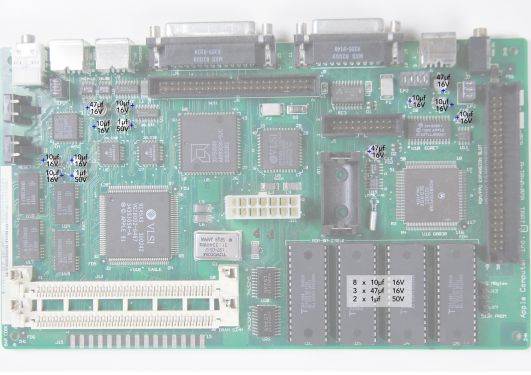 Classic II 13-capacitor logic board (Recap-a-Mac)
 -
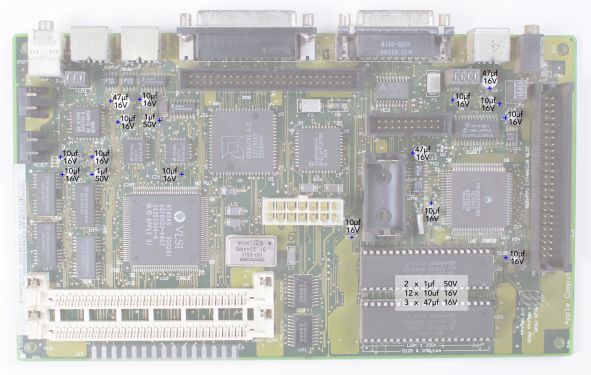 Classic II 17-capacitor logic board (Recap-a-Mac)
_recapping.jpg)
_Recapping.jpg)
Power/sweep board
editThe Classic and Classic II share this board.[10] Apple lists four field-replaceable versions: 661-0597 (110 V, Rev. A), 661-0599 (220 V, Rev. A), 661-0651 (110 V, Rev. B) and 661-0652 (220 V, Rev. B).[5] Rev. A and Rev. B boards are not interchangeable: each must be used with the matching CRT yoke assembly.[11]
Identify the mains version first
edit| | The primary reservoir capacitor CP1 is 250 V on a 110 V board and 400 V on a 220–240 V board. 240 V mains rectifies to about 340 V DC. A 250 V part at CP1 on a board where CP1 alone takes the full rectified mains is over its rating. |
The bare boards carry 630- numbers. What the sources show for the mains input of each:
| Board | Source | CP1 | CP13 | Notes |
|---|---|---|---|---|
| 630-0395 | Console5; BOMARC 820-0395-A ("early") | 220 µF 250 V | 220 µF 250 V | Voltage doubler; JP1 is a wire link marked "cut for 220 VAC input"; +306 V across the pair |
| 630-0420 | Console5 (240 V version of the 630-0395 list) | 220 µF 400 V | 220 µF 400 V | |
| 630-0525 | Console5; BOMARC 820-0525-A ("late") | 220 µF 250 V | 220 µF 250 V | JP1 marked "cut for 240 VAC input"; +306 V across the pair |
| 630-0560 (120 V list) | Console5 | 220 µF 250 V | 220 µF 250 V | |
| 630-0560 (240 V list) | Console5 | 220 µF 400 V | jumper, no capacitor |
Sources: Console5's board pages,[12][13][14] and BOMARC's schematics for 630-0395 and 630-0525.[3] Recap-a-Mac's photograph of a 220–240 V board shows one 220 µF 400 V capacitor and no 250 V electrolytic.[10]
To identify a board: read the 661- label or the 630- number, look at CP1's printed rating, and check whether CP13 is a capacitor or a wire link. If CP13 is a link, CP1 must be a 400 V part.
Later layout (630-0525 and the 630-0560 240 V list)
edit| Reference | Capacitance | Voltage |
|---|---|---|
| CF1 | 47 µF | 25 V |
| CF2 | 220 µF | 16 V |
| CF3 | 1000 µF | 16 V |
| CF4 | 470 µF | 25 V |
| CL1 | 1000 µF | 25 V |
| CL2 | 4.7 µF | 250 V |
| CL3 | 1 µF | 50 V |
| CL11 | 47 µF | 16 V |
| CP1 | 220 µF | 250 V (630-0525); 400 V (630-0560, 240 V) |
| CP2 | 470 µF | 50 V |
| CP3 | 10 µF | 25 V |
| CP4 | 47 µF | 25 V |
| CP5 | 1 µF | 50 V |
| CP6 | 2200 µF | 10 V |
| CP7 | 1000 µF | 10 V |
| CP8 | 2200 µF | 16 V |
| CP9 | 470 µF | 25 V |
| CP10 | 470 µF | 25 V |
| CP11 | 220 µF | 50 V |
| CP12 | 1000 µF | 16 V |
| CP13 | 220 µF 250 V (630-0525); jumper, no capacitor (630-0560, 240 V) | |
| CP34 | 1 µF | 50 V |
| CP36 | 2200 µF | 10 V |
| CP37 | 1 µF | 50 V |
| CV2 | 470 µF | 10 V |
From Console5's lists for 630-0525 and the 630-0560 240 V version, which differ only at CP1 and CP13.[13][14] Recap-a-Mac's guide for a 240 V board agrees on every value and quantity except the 1 µF 50 V parts, where it marks two and Console5 lists four (CL3, CP5, CP34, CP37).[10]

Earlier layout (630-0395)
edit| Reference | Capacitance | Voltage |
|---|---|---|
| CF1 | 47 µF | 25 V |
| CF2 | 220 µF | 16 V |
| CF3 | 1000 µF | 16 V |
| CF4 | 470 µF | 25 V |
| CL1 | 10 µF | 50 V |
| CL2 | 4.7 µF | 250 V |
| CL3 | 1 µF | 50 V |
| CP1 | 220 µF | 250 V |
| CP2 | 1000 µF | 35 V |
| CP3 | 10 µF | 25 V |
| CP4 | 47 µF | 25 V |
| CP5 | 1 µF | 50 V |
| CP6 | 2200 µF | 10 V |
| CP7 | 1000 µF | 10 V |
| CP8 | 2200 µF | 16 V |
| CP9 | 470 µF | 25 V |
| CP10 | 470 µF | 25 V |
| CP11 | 220 µF | 25 V |
| CP12 | 1000 µF | 16 V |
| CP13 | 220 µF | 250 V |
| CP31 | 1000 µF | 6.3 V |
| CP34 | 1 µF | 50 V |
| CP35 | 1 µF | 50 V |
| CP36 | 2200 µF | 10 V |
| CP37 | 1 µF | 50 V |
From Console5's list for 630-0395.[12] Console5 notes three differences on related boards: on 630-0420 (240 V) CP1 and CP13 are 220 µF 400 V; on its 630-0560 120 V list CP2 is 470 µF 50 V and CP11 is 220 µF 50 V.[12][14] The values that appear on BOMARC's 630-0395 drawing (CP1, CP3, CP4, CP5, CP9, CP11, CP13, CP34, CP35, CP37, CF4) agree with this list.[3]
Fuse, adjustment and other parts
editApple's Service Source shows how to pull the fuse but prints no rating.[15] The rating is on the board: Recap-a-Mac's photograph of a 240 V board shows "FP1 T3.15A/250V" printed beside the fuse holder, and BOMARC's drawings give GMA-3 on 630-0395 and GMA-3.15 on 630-0525.[10][3] Replace like for like with what your own board specifies.
Apple publishes no voltage adjustment for this machine; its Adjustments chapter covers light meter setup, video and yoke.[16] Recap-a-Mac says the output can be adjusted with the variable resistor PP1.[10] On BOMARC's drawings PP1 is marked "VOLT ADJ" and sits in the TL431 feedback network of the TDA4605 switching controller.[3]
Recap-a-Mac also reports cracked solder joints, corrosion and shorts from capacitor leakage, and failures of the DIP ICs it calls IF1, QP1 and JP1.[10] On BOMARC's drawings QP1 is the CNY17 opto-coupler in the supply's feedback loop and JP1 is the mains link described above, so check designators against your board before ordering parts.[3]
Replacement parts
editFor the logic board, Recap-a-Mac fits KEMET solid tantalum parts at the original values: T491B105K050AT for 1 µF 50 V and T491D476K016AT for 47 µF 16 V.[6] Solid tantalum contains no liquid electrolyte. Its stripe marks the positive terminal, the opposite of an aluminium electrolytic, and a reversed tantalum fails short.
For the power/sweep board, fit 105 °C aluminium electrolytics at the listed capacitance and at least the listed voltage.
Replacement procedure
edit- Remove the logic board and take the battery out of its holder.[4]
- Discharge the CRT before touching the power/sweep board. See CRT Discharge Procedure.
- Confirm with a meter that CP1 (and CP13) have discharged before working on the primary side.
- Remove the surface-mount capacitors by alternating heat between the terminals or with hot air. Twisting a can off cold lifts the pads.
- Clean the board with isopropyl alcohol and a soft brush until a clean swab comes away clean.
- Check continuity along every trace that ran under or beside a capacitor and repair breaks before fitting anything.
- Fit the new parts the right way round.
- Check each rail for shorts to ground before applying power.
Tools are listed on Recommended Tools.
After the recap
editApple publishes no rail tolerances for the Classic II.[16] Check the rails at the logic board power connector against their nominal values. BOMARC's drawing of the Classic II board gives the connector's pins: +12 V on pin 1, +5 V on pins 2 and 3, −12 V on pin 8, ground on pins 10–14.[9] Apple's symptom chart sends clicking, chirping or thumping first to this cable being properly seated on the logic board (J12 in Apple's numbering), then to the power/sweep board.[17]
Module part numbers
editFrom Apple's exploded view for the Classic, Classic II and Performa 200:[5]
| Module | Apple part number |
|---|---|
| Logic board, Classic II and Performa 200 (2 MB) | 661-0672 |
| Logic board, Classic (1 MB) | 661-0596 |
| Power/sweep board | 661-0597, 661-0599, 661-0651, 661-0652 (see above) |
| Lithium battery | 742-0011 |
| CRT and yoke assembly | 076-0546 |
| Floppy drive | 661-0474 |
Related pages
editReferences
edit- ↑ 1.0 1.1 1.2 Recap-a-Mac, "Macintosh Classic II (Rev A)": capacitor and battery leakage; earlier board with four ROM chips and 13 surface-mount electrolytics, later board with two ROM chips and 17. Secondary source.
- ↑ Apple Computer, Apple Service Guide for Macintosh Computers, Volume II (Apr 1992), Safety p. 3 (PDF p. 5). Hosted as File:APPLE MACINTOSH SERVICE GUIDE VOL2 1992.pdf.
- ↑ 3.0 3.1 3.2 3.3 3.4 3.5 BOMARC Services, schematics of the "Macintosh Classic" series computer power supply / 9-inch monitor: board 820-0395-A "early" (Apple/Samsung, sheets 1–2, June 1992) and board 820-0525-A "late" (Apple/Hitachi, sheets 1–2, December 1991), PDF pp. 1–2 and 4–5 of File:MacintoshClassic LogicBoard Schematic.pdf. Sheet 1 of each: KBL08 bridge DP9, CP1 and CP13 220 µF 250 V, wire link JP1 marked "cut for 220 VAC input" (0395) or "cut for 240 VAC input" (0525), +306 V measured to primary ground, fuse GMA-3 (0395) or GMA-3.15 (0525), TDA4605 controller IP1, CNY17 opto-coupler QP1, TL431 DP14 with PP1 "VOLT ADJ", 7812 IP4, 79L12 IP3. Reverse-engineered, not Apple documentation.
- ↑ 4.0 4.1 4.2 Apple Computer, Macintosh Classic/Classic II/Performa 200 Service Source (115-page copy, File:Classic ii.performa 200.pdf), Additional Procedures, Battery Verification and Battery Replacement pp. 1–8 (PDF pp. 81–88).
- ↑ 5.0 5.1 5.2 Apple, Macintosh Classic/Classic II/Performa 200 Service Source, Exploded View (PDF p. 115): logic boards 661-0596 (1 MB, Classic) and 661-0672 (2 MB, Classic II, Performa 200); power/sweep boards 661-0597 (110 V, Rev. A), 661-0599 (220 V, Rev. A), 661-0651 (110 V, Rev. B), 661-0652 (220 V, Rev. B); lithium battery 742-0011; CRT and yoke assembly 076-0546; floppy drive 661-0474.
- ↑ 6.0 6.1 Recap-a-Mac, "Macintosh Classic": PRAM battery failure; KEMET T491B105K050AT (1 µF 50 V) and T491D476K016AT (47 µF 16 V) tantalum replacements. Secondary source.
- ↑ Console5 TechWiki, "Macintosh Classic II": logic board 630-0055-B / 820-0326-B or 630-0401-B / 820-0401-B. Secondary source (a capacitor-kit list).
- ↑ Recap-a-Mac, "Macintosh Classic II (Rev B)". Secondary source.
- ↑ 9.0 9.1 BOMARC Services, schematic of Apple 820-0401-B "Classic II" computer motherboard, sheet 1. Hosted as File:Macintosh Classic II Schematic.pdf. Reverse-engineered, not Apple documentation.
- ↑ 10.0 10.1 10.2 10.3 10.4 10.5 Recap-a-Mac, "Macintosh Classic I + II Analog Board (220V – 240V version)": shared board; guide photographed from a 220–240 V board, with an earlier revision differing in one or two capacitors; cracked joints, leakage damage, DIP IC failures (IF1, QP1, JP1); voltage adjustment with PP1. Secondary source.
- ↑ Apple, Macintosh Classic/Classic II/Performa 200 Service Source, Take Apart, Power/Sweep Board pp. 10–11 (PDF pp. 39–40).
- ↑ 12.0 12.1 12.2 Console5 TechWiki, "Mac Analog Board: 630-0395" (with the 630-0420 and 630-0560 differences noted in the list). Secondary source.
- ↑ 13.0 13.1 Console5 TechWiki, "Mac Analog Board: 630-0525". Secondary source.
- ↑ 14.0 14.1 14.2 Console5 TechWiki, "Mac Analog Board: 630-0560": separate 120 V and 240 V lists; on the 240 V list CP1 is 220 µF 400 V and CP13 is "JUMPER - No cap installed". Secondary source.
- ↑ Apple, Macintosh Classic/Classic II/Performa 200 Service Source, Take Apart, Fuse pp. 36–37 (PDF pp. 65–66).
- ↑ 16.0 16.1 Apple, Macintosh Classic/Classic II/Performa 200 Service Source, Adjustments pp. 1–24 (PDF pp. 90–113).
- ↑ Apple, Macintosh Classic/Classic II/Performa 200 Service Source, Troubleshooting, Symptom Charts, Miscellaneous p. 12 (PDF p. 25).