

Amstrad GX4000
 | |
| GX4000 with a paddle controller | |
| Specifications | |
|---|---|
| Manufacturer | Amstrad plc |
| Type | Game console |
| Released | September 1990 |
| Discontinued | 1991 |
| Intro price | £99.99 (UK launch) |
| CPU | Zilog Z80A (Z8400AB1N) at 4 MHz |
| Memory | 64 KB RAM |
| Storage | — |
| Display | 160 × 200 (16 colours), 320 × 200 (4) or 640 × 200 (2) from 4,096 |
| Sound | General Instrument AY-3-8912, three voices |
| Graphics | Amstrad ASIC (AMS40489) |
| Media | ROM cartridge, up to 512 KB |
| Power | 11 V DC adaptor, or 5 V from an MM12 or CM14 monitor |
| Dimensions | 250 × 44 × 184 mm |
| OS / Firmware | — |
| Model no. | GX4000 |
The Amstrad GX4000 is a cartridge games console that Amstrad launched in Europe in September 1990, alongside the Amstrad 464 Plus and Amstrad 6128 Plus computers. It uses the same ASIC, Z80A processor, 64 KB of RAM and AY-3-8912 sound chip as the Plus computers, without a keyboard, cassette deck or disc drive. Amstrad's service manual covers the three machines together, with a separate GX4000 section.[1] The console sold poorly and was discontinued in 1991.[2]
History
[edit | edit source]Amstrad announced the GX4000 with the 464 Plus and 6128 Plus at the CNIT in Paris in August 1990. It went on sale a month later in Britain, France, Spain and Italy at £99.99 in Britain and 990 francs in France, with two paddles, a power adaptor and the racing game Burnin' Rubber.[2] Wikipedia records that many of its games were CPC titles repackaged on cartridge, that it sold poorly against Sega and Nintendo consoles, and that it was discontinued in 1991.[2]
Hardware
[edit | edit source]Amstrad's specification lists a Z80 at 4 MHz, 64K of RAM, a 128K ROM cartridge holding Burnin' Rubber, the GI AY-3-8912 sound chip and an ASIC of 18,000 gates that emulates the 6845 video controller and the 8255 parallel interface and holds 16,000 bits of sprite storage. Cartridges can hold up to 512K. All three display modes have 16 hardware sprites, and screen and sprite colours come from a palette of 4,096. The specification also lists soft scrolling, split screen, raster interrupts and DMA-driven sound.[1]
| Ref | Part | Description in the parts list |
|---|---|---|
| IC1 | AMS40489 | Gate array |
| IC2 | Z8400AB1N | CPU |
| IC8 | MC74HC4051N | Analogue multiplexer |
| IC9 | LA6393D | Dual op amp |
| IC10, IC11 | KM41464AP-12 | RAM |
| IC14 | AY-3-8912 | Sound generator |
| IC15 | AMS40464 | Video DAC |
| IC16 | PC74HCT02P | Quad NOR gate |
| IC17 | µPC78L05 | 5 V 0.1 A regulator |
| IC101 | CXA1145P | RGB encoder |
| IC102 | UM1234E36 | RF modulator |
| IC181 | L7805 | 5 V 1 A regulator |
| IC401, IC402 | AMS40982, AMS40908 | Cartridge gate arrays |
The main board is PCB ASSY MC0123. The parts list gives the crystal X1 as a 39.9025 MHz CXO-824C and two ceramic oscillators, X101 (6.0 MHz) and X102 (5.5 MHz).[1] The board drawn in the manual is marked MC0123A, 2700-017P-3; a board photographed for Wikimedia Commons is marked MC0123C, 2700-017P-4, so more than one revision was made.[1][3] The cartridge connector, CE101, is on the main board.[1][3]
The GX4000 and the Plus computers share the AMS40489 ASIC, the Z80A, the KM41464AP-12 RAMs, the AY-3-8912 and the AMS40464.[1] The Plus pages, starting at the Amstrad 464 Plus, describe the common hardware in more detail.

Connectors
[edit | edit source]| Socket | Use |
|---|---|
| 3.5 mm stereo jack | External amplifier |
| Two 9-pin D-type | Digital paddles or joysticks |
| 15-pin D-type | IBM-standard analogue joystick |
| RJ11 | Light gun (labelled "auxiliary control device" in the user instructions) |
| Phono | UHF television lead (supplied) |
| 8-pin DIN | RGB, sync, luminance and stereo sound to an Amstrad monitor |
| 21-pin Scart/Peritel | Direct connection to a television |
| 6 mm socket, 5 V | Power from an MM12 or CM14 monitor |
| 6 mm socket, 11 V | Power from the supplied AC adaptor |
There is also a sound switch on the rear and a pause button and power/interlock switch on the top.[1][4] The user instructions give the pinouts of the RJ11, paddle and monitor sockets on p. 7. Pin 9 of the second paddle socket is not COM2.[4]
Power
[edit | edit source]The GX4000 has two DC inputs. The 5 V socket J101 takes power from an MM12 or CM14 monitor through the filter L1 and the power switch SW1. The 11 V socket J102 takes the AC adaptor, and an L7805 regulator, IC181, produces 5 V from it. On the UK board a µPC78L05, IC17, supplies the RF modulator from the same input, and a diode, a 470 µF capacitor, a 33 Ω resistor and a 12 V zener (D181, C182, R181, D180) make a separate +10 V line.[1] The supplied UK adaptor is labelled GX4000 PSU/UK, input 240 V 50 Hz, output 11 V DC 500 mA.[5] Amstrad's specification lists 220 V adaptors for Europe and 240 V adaptors for the UK, with separate part numbers in the parts list (270973 Euro, 270974 UK).[1]
Amstrad's user instructions and a label on the adaptor both say to connect the DC plug to the console before plugging the adaptor into the mains, and to use only the supplied adaptor or power from an MM12 or CM14 monitor.[4][5]
Board variants
[edit | edit source]The service manual has separate drawings for a France board: its own PCB views, power regulator schematic and output interface schematic (pp. 32–35). The France regulator drawing has no IC17; the modulator supply is taken from the 5 V line through link LK7.[1] Check which board is fitted before working from the schematics.
Repair guides
[edit | edit source]- Amstrad GX4000 Maintenance Guide – opening the case, the cartridge slot, connectors and the RF adjustment
- Amstrad GX4000 Troubleshooting Guide – power, picture, sound and cartridge faults
- Amstrad GX4000 Capacitor Replacement Guide – the electrolytic capacitors from Amstrad's parts list
Documentation
[edit | edit source]- Amstrad GX4000 Service Manual – Amstrad's Plus range service manual, split scan; GX4000 section on printed pages 23–36
- Amstrad 464 Plus / 6128 Plus / GX4000 Service Manual – the same manual, single-page scan
- Amstrad GX4000 User Instructions – Amstrad's user instructions in English, Spanish, Italian and French
Gallery
[edit | edit source]-
 Rear: DC inputs, monitor DIN, Peritel, sound switch and UHF socket
-
 The UK adaptor, 11 V DC 500 mA
-
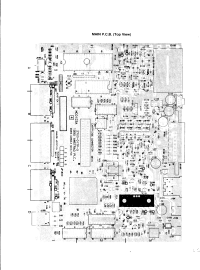 Main PCB MC0123A, service manual p. 24


Related pages
[edit | edit source]References
[edit | edit source]- ↑ 1.00 1.01 1.02 1.03 1.04 1.05 1.06 1.07 1.08 1.09 Amstrad plc, 464 PLUS Home Computer / 6128 PLUS Home Computer / GX4000 Games Console / MM 12 Monochrome Monitor / CM 14 Colour Monitor Service Manual, GX4000 section. Hosted as File:Amstrad GX4000 Service Manual.pdf, described at Amstrad GX4000 Service Manual. Note to engineers p. 2; GX4000 technical specification and electrical adjustment p. 23; main PCB top view p. 24; power regulator schematic p. 29; cabinet exploded view and parts list p. 31; France board pp. 32–35; electrical parts list p. 36.
- ↑ 2.0 2.1 2.2 Wikipedia, "GX4000", lead and sections "Launch" and "Commercial failure". Retrieved 2026-10-02. Announcement in Paris in August 1990, launch in Britain, France, Spain and Italy in September 1990, prices of £99.99 and 990 francs, the bundled Burnin' Rubber, and discontinuation in 1991.
- ↑ 3.0 3.1 Evan-Amos, "Amstrad-GX4000-Motherboard-Flat-Top.jpg", Wikimedia Commons, 2017 (public domain). Retrieved 2026-10-02. Board markings MC0123C and 2700-017P-4, the Astec UM1234 E36 modulator and the cartridge connector CE101 on the main board.
- ↑ 4.0 4.1 4.2 Amstrad plc, GX4000 User Instructions (1990). Hosted as File:Amstrad GX4000 User Instructions.pdf, described at Amstrad GX4000 User Instructions. English section: looking after the console p. 1, features p. 2, TV connection p. 3, operation p. 5, problem solving p. 6, connector pinouts p. 7.
- ↑ 5.0 5.1 Evan-Amos, "Amstrad-GX4000-Power-Supply.jpg", Wikimedia Commons, 2017 (public domain). Retrieved 2026-10-02. Rating label and connection warning on the UK adaptor.

