

Atari 7800
 | |
| A North American Atari 7800 with its Pro-Line joystick | |
| Specifications | |
|---|---|
| Developer | General Computer Corporation[1] |
| Manufacturer | Atari Corporation[1] |
| Type | Home video game console |
| Released | May 1986 (North America); September 1989 (United Kingdom)[1] |
| Discontinued | 1992[1] |
| Intro price | US$79.95 (1986)[1] |
| CPU | Atari SALLY, a modified 6502 (Atari C014806), 1.79 MHz[1][2] |
| Memory | 4 KB (two 2K × 8 static RAMs, U5 and U6)[3] |
| Storage | ROM cartridge |
| Display | MARIA graphics chip |
| Sound | TIA, 2 channels |
| OS / Firmware | BIOS ROM (U7)[3] |
| Predecessor | Atari 5200, Atari 2600 |
The Atari 7800 ProSystem is a home video game console designed by General Computer Corporation (GCC) for Atari, Inc. Atari announced it on 21 May 1984. After Jack Tramiel bought Atari's consumer division in July 1984 the launch was shelved, and Atari Corporation released the console nationwide in the United States in May 1986 at US$79.95.[1] It plays almost all Atari 2600 cartridges as well as its own. Graphics come from GCC's MARIA chip, and sound and the controller and switch inputs come from the 2600's TIA and 6532.[1][3]
Fault-finding is on the Atari 7800 Troubleshooting Guide; capacitor values are on the Atari 7800 Capacitor Replacement Guide.
Models and board revisions
[edit | edit source]| Version | Board | Notes |
|---|---|---|
| NTSC, expansion port (1984 to 1987) | C025233-001; some later units C025233-002 | Unused expansion port on the left side. Units built in 1984 and 1985 were warehoused until the 1986 launch |
| NTSC, no expansion port (1987 to 1992) | C025233-002 | The port is left off, though its footprint remains on the board |
| PAL (1989 to 1993) | C300633-001 | Different faceplate, green power LED, Asteroids built into the BIOS, no cartridge signature check. French consoles have an RGB connector in place of the RF output |
All NTSC consoles check a digital signature in a 7800 cartridge before running it in 7800 mode; a cartridge without one runs in 2600 mode.[4][1] Some C025233-002 boards carry an extra timing circuit around a 74LS02 (U13). ConsoleMods says it was added to fix 2600 compatibility with titles such as Kung-Fu Master and Dark Chambers, but breaks some Activision 2600 games, among them The Activision Decathlon, Robot Tank and Space Shuttle. Some -002 boards have only a 0 Ω jumper where the circuit would be.[4]
Atari's schematic for the NTSC console is drawing C025231-001, revision A, from 1984.[3]
Hardware
[edit | edit source]| Location | Device | Marking on a 1986 board |
|---|---|---|
| U1 | MARIA graphics chip | VTI VC2049B, C024674-30 |
| U2 | 6502 CPU (SALLY) | NCR, C014806C-29 |
| U5, U6 | 2K × 8 static RAM (6116) | Sony CXK5816PN-10L |
| U7 | BIOS ROM, 24 or 28 pins | NCR 2333-30, C024922B-29 |
| U8 | TIA | AMI C010444D-01 |
| U9 | 6532 RIOT | Rockwell R6532-15, C010750-12 |
| U10 | 4013 dual flip-flop (power latch and reset) | |
| U11 | 74LS174 | |
| U3, U4, U12 | 74LS32 and 74LS08 gates | |
| VR1 | 7805 regulator |
Locations are from Atari's schematic;[3] the markings were read from a photograph of an NTSC board on Wikimedia Commons;[2] the gate types are from Console5.[5] The schematic allows a 24-pin or 28-pin ROM at U7, chosen by jumpers W1 and W2.[3] Wikipedia gives the BIOS as 4 KB on NTSC consoles and 16 KB, including Asteroids, on PAL consoles.[1]
A 14.31818 MHz crystal (Y1) with Q3 and Q4 forms the master oscillator, which drives MARIA.[3]
Power
[edit | edit source]The console runs from an external DC adaptor plugged into J5. Atari's owner's manual tells owners to use only the adaptor packed with the console.[6] On the schematic:[3]
- The input passes ferrite FB2 to the 2200 µF reservoir C62.
- U10, a 4013, is a power latch. It is always powered, from the unregulated input through R53 (310 Ω) and a 5.1 V zener (1N5231, or a 4.7 V 1N5230). The power button S1 clocks it at pin 3.
- The latch drives Q9 (2N3904), which switches Q10 (MJE210), the pass transistor that feeds the 7805 regulator VR1. CR6 (1N914) sits across the regulator, and C61 (220 µF) filters its output.
- A second 220 µF capacitor, C22, sits on the +5 V rail among the chip bypass capacitors.
Video and sound
[edit | edit source]MARIA and the TIA each produce luminance, sync and colour outputs, and only one set is active at a time. The luminance and sync lines are combined in gates (U3) and summed through R10, R11, R12, R13 and R15; MARIA's colour (R16, 4.3 kΩ) and the TIA's colour (R17, 4.7 kΩ) join through L1 (47 µH) and C8 (47 pF). The result, CVIDEO, goes to pin 3 of the RF modulator RF1.[3][7] The modulator on the photographed board is marked C024629, VM-61 Biwave, Taiwan.[2]
The TIA's audio outputs are mixed with an audio line from the cartridge connector (J1 pin 18), so a cartridge can add its own sound chip.[3][1] Q1 (2N3563) with C4 and C5, both 820 pF, forms the sound-carrier oscillator.[3]
Expansion port
[edit | edit source]| Pin | Signal | Pin | Signal | Pin | Signal |
|---|---|---|---|---|---|
| 1 | Ground | 7 | OSCDIS | 13 | MLUM1 |
| 2 | +5 V | 8 | EXTMEN | 14 | MLUM2 |
| 3 | CVIDEO (composite video) | 9 | Ground | 15 | MCOL |
| 4 | MLUM0 | 10 | EXTOSC | 16 | RDY |
| 5 | MLUM3 | 11 | CLK2 | 17 | Audio |
| 6 | BLANK | 12 | MSYNC | 18 | Ground |
ConsoleMods says the port was meant for a planned laserdisc add-on and carries mostly video signals, with no connection to the main system bus.[4]
Capacitors
[edit | edit source]The NTSC board has three aluminium electrolytics: C62 (2200 µF, power input), C61 (220 µF, regulator output) and C22 (220 µF, +5 V rail).[3] Console5 gives all three as 16 V parts.[5] Details are on the Atari 7800 Capacitor Replacement Guide.
Known faults
[edit | edit source]From ConsoleMods' troubleshooting page, a community source:[8]
- No power LED: a broken lead in the thin original adaptor cable, a dirty power tact switch (all four console buttons are 12 × 12 mm tact switches), a failed 7805, or a leaking or blown 2200 µF capacitor.
- Cannot be switched off: the 4013 power latch U10, then the MJE210 pass transistor Q10.
- Black or scrambled screen: dirty cartridge contacts, or traces worn through under the lower right corner of the cartridge port shroud.
- A PAL 7800 cartridge will not run on an NTSC console, because the NTSC BIOS rejects it.
The Atari 7800 General Maintenance page covers cleaning and these parts in more detail.
Documentation
[edit | edit source]AtariAge members report that Atari did not issue a field service manual for the 7800. The service material that survives is the schematic, a repair flowchart, and a theory of operation and parts list shared on AtariAge.[9]
- Atari 7800 Documentation: the schematic, repair flowchart and owner's manual hosted here.
- Schematic Diagram 7800, C025231-001 Rev. A (1984).
- 7800 repair flowchart, six sheets.
- Atari 7800 ProSystem owner's manual, C024819-001 Rev. A.
Gallery
[edit | edit source]-
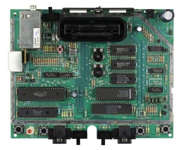 NTSC 7800 board with the shields removed
 -
 With the top case removed


Related pages
[edit | edit source]- Atari 7800 General Maintenance
- Atari 7800 Troubleshooting Guide
- Atari 7800 Capacitor Replacement Guide
- Atari 7800 Composite Mod
- Atari 7800 Documentation
- Atari 2600
- Atari 2600 Jr
References
[edit | edit source]- ↑ 1.00 1.01 1.02 1.03 1.04 1.05 1.06 1.07 1.08 1.09 1.10 Wikipedia, "Atari 7800", introduction, history, technical specifications and backward compatibility sections. en.wikipedia.org. Used for history, dates, prices and the BIOS sizes.
- ↑ 2.0 2.1 2.2 Evan-Amos, photograph of an NTSC Atari 7800 motherboard, Wikimedia Commons, public domain; chip markings read from the image. Hosted here as File:Atari 7800 motherboard.jpg.
- ↑ 3.00 3.01 3.02 3.03 3.04 3.05 3.06 3.07 3.08 3.09 3.10 3.11 Atari, Inc., Schematic Diagram 7800, drawing C025231-001 Rev. A, 1984. Hosted here as File:Atari 7800 Schematic Diagram C025231-001.pdf.
- ↑ 4.0 4.1 4.2 ConsoleMods Wiki, "Atari 7800: Atari 7800 Model Differences" (revision of 5 October 2025). Community reference, CC BY 4.0.
- ↑ 5.0 5.1 Console5 TechWiki, "Atari 7800", chip info and capacitor list. Secondary source (a capacitor-kit vendor's component list).
- ↑ Atari Corp., Atari 7800 ProSystem owner's manual, C024819-001 Rev. A, 1986: set-up and "Maintaining your Atari 7800 ProSystem". Hosted here as File:Atari 7800 ProSystem Owner's Manual.pdf.
- ↑ 7800 repair flowchart, sheet E (video checks: MARIA video lines on pins 42 to 48, TIA lines on pins 2, 5, 7, 8 and 9; CVIDEO on pin 3 of the RF can). Hosted here as File:Atari 7800 Repair Flowchart.pdf.
- ↑ ConsoleMods Wiki, "Atari 7800: General Troubleshooting" (revision of 30 August 2025). Community reference, CC BY 4.0.
- ↑ "7800 Repair manual...", AtariAge Forums, Atari 7800, thread started by DavidMil, with replies pointing to the 7800 diagnostic cartridge, a theory-of-operation archive and Mitch's parts list. forums.atariage.com. Community statement.