

Amstrad PPC640
 | |
| PPC640 opened out, with the LCD raised | |
| Specifications | |
|---|---|
| Manufacturer | Amstrad plc |
| Type | Portable computer |
| Released | 1987 |
| Intro price | US$1,099 (1987)[1] |
| CPU | Sony CXQ70116P-8 (NEC V30 type), 8 MHz |
| Memory | 640 KB with parity; 64 KB video RAM |
| Storage | One (PPC640S) or two (PPC640D) 720 KB 3.5-inch drives |
| Display | 640 × 200 supertwist LCD, not backlit; MDA and CGA compatible |
| Sound | Speaker with volume control |
| ROM | 16 KB system ROM (ROS) |
| Ports / interface | RS-232 serial, Centronics parallel, 9-pin video, expansion A and B, 14-way DIN monitor power, telephone line |
| Power | Ten alkaline C cells, AC adaptor, car adaptor or Amstrad PC monitor |
| Dimensions | 450 × 230 × 100 mm closed, excluding handle |
| Weight | 5.4 kg without batteries |
| OS / Firmware | MS-DOS 3.30, Mirror II, PPC Organizer |
| Model no. | PPC640S, PPC640D |
The Amstrad PPC640 is a portable IBM PC compatible that Amstrad released in 1987 alongside the PPC512. It has 640 KB of RAM, an 8 MHz V30-type processor, a non-backlit supertwist LCD, a full-size 102-key keyboard that folds up over the screen to form the lid, one or two 720 KB 3.5-inch drives and a built-in Hayes-compatible modem. It runs from ten C cells, a mains adaptor, a car adaptor or the power supply in an Amstrad PC1512 or PC1640 monitor.[2][3] The PPC512 is the same machine with 512 KB and no modem.[2]
History
[edit | edit source]The PPC512 and PPC640 were Amstrad's first portable PC compatibles and were developed from the desktop PC1512 and PC1640.[3] Amstrad's Technical Reference Manual for the pair was first published in 1987.[4] Both models came with MS-DOS 3.30 and PPC Organizer, a memory-resident diary, card file, word processor and calculator, and the PPC640 added the Mirror II communications program.[3][5] The machine was sold with a nylon carry bag with pockets for the adaptors, manuals and discs.[5] In 1988 Amstrad used the PPC design as the basis of a desktop machine, sold as the Amstrad PC20 and the Sinclair PC200.[3]
PPC640 and PPC512
[edit | edit source]| Item | PPC640 | PPC512 |
|---|---|---|
| RAM | 640 KB | 512 KB |
| Modem | Built in (modem board MC0053A, part 177322) | None |
| Mirror II communications software | Supplied | Not supplied |
| Floppy drive part number | 177248 | 177247 |
| Keyboard switch assembly | 177319 | 177318 |
Both come as S (single drive) and D (twin drive) versions. The cabinet parts list gives most case parts, including the battery lid (177222 on the PPC640, 177221 on the PPC512), a separate PPC640 number, and has separate bottom assemblies for the S and D versions. The LCD, the CPU board, the power supply and memory board, and the small fuse, LED and volume boards carry the same part numbers on both models.[2]
Hardware
[edit | edit source]Processor and memory
[edit | edit source]Amstrad's specification sheet and Technical Reference Manual call the processor an 8086 running at 8 MHz, with a socket for an 8087 maths co-processor.[2][4] The electrical parts list gives the processor, IC120, as a CXQ70116P-8 (part 177284), Sony's 8 MHz part of the NEC V30 family.[2][6]
The 640 KB of system RAM is parity-checked; the 16 KB system ROM (the ROS) is not.[4] The parts list gives eighteen KM41256-15 DRAMs (IC135–152) and six KM4164B-15 (IC153–158).[2] MCbx's guide to upgrading a PPC512 to 640 KB fits four 41464 (64K × 4) and two 4164 chips in six empty positions on the lower board, then moves the 512K/640K link LK4 on the memory board and a second link on the CPU board.[7] Read the chip markings on the board before ordering parts, since the two sources describe those positions differently.
Boards
[edit | edit source]The parts list names these boards:[2]
| Reference | Board | Part number |
|---|---|---|
| PCB101 | CPU board MC0051A | 177259 |
| PCB102 | Switch (micro) | 177320 |
| PCB103 | Switch | 177255 |
| PCB104 | LED | 177249 |
| PCB501 | Memory and power supply MC0057A | 177257 |
| PCB502 | Fuse | 177251 |
| PCB503 | Volume control | 177253 |
| PCB504 | Control | 177321 |
| PCB901 | Modem MC0053A | 177322 |
The power supply schematic shows the battery holder on PCB102 (MS0091), the switch that closes when the keyboard is shut on PCB103 (MS0093), fuses F501 and F502 on PCB502 (MS0094), and the −20 V LCD drive on PCB504 (MS0096A). It labels the main power board PCB501 MC0052A, where the parts list says MC0057A.[2]
Display
[edit | edit source]The internal display adapter emulates both the MDA and the CGA, and drives either the internal LCD or an external monitor through a 9-pin D socket carrying RGBI colour, mono video and the two sync signals.[4] The LCD is a 640 × 200 supertwist panel with adjustable contrast and grey-scale emulation; it tilts on its own hinge and folds into a recess in the top of the case.[2][3] With Scroll Lock on, the right-hand Alt (Gr) key switches between two ways of rendering colour on the LCD, and the right-hand Ctrl key switches output between the LCD and an external monitor.[8] Amstrad treated the LCD as a complete exchange unit (LCD101, part 177245) and gave no service data for it.[2]
Discs
[edit | edit source]The drives are Amstrad's FD-5 720 KB 3.5-inch units, driven by a µPD765A-type controller clocked at 4 MHz; the drive nearest the keyboard is drive A.[2][4][8] There is no hard disc interface inside the machine. External hard disc controllers and a bus expansion unit use the expansion connectors.[4]
Ports
[edit | edit source]| Connector | Type | Notes |
|---|---|---|
| Serial (COM1) | 25-way D plug | DTE, INS8250 UART at 3F8h, IRQ4 |
| Parallel | 25-way D socket | Centronics printer port at 378h |
| Video | 9-way D socket | RGBI colour or mono video with sync |
| Expansion A | 25-way D socket | Part of the 8-bit expansion bus |
| Expansion B | 37-way D socket | Rest of the expansion bus, with power inputs |
| DC input | Jack | 12 V nominal, centre positive, 9.5–17.5 V |
| Monitor power | 14-way DIN | +5, +12, −5 and −12 V from an Amstrad PC monitor; no video |
| Modem | BT 431A in a covered compartment right of the LCD (UK) | 603A extension socket at the right rear |
The US PPC640 has two Bell connectors, LINE and PHONE, at the rear of the modem instead of the British connectors.[4][8] On US machines a metal plate covers the expansion connectors.[4]
Modem
[edit | edit source]The PC2000 modem sits on its own board, PCB901 (MC0053A), and appears to software as COM2: an INS8250 UART at 2F8h on IRQ3.[2][4] Amstrad's specification lists V21 (300 bps), V23 (1200/75 bps), V22 (1200 bps) and V22bis (2400 bps), with Hayes commands, auto-dial and auto-answer; the US manual lists Bell 103 and 212A and V22bis.[2][8] The modem schematics show Rockwell R5325 and R5310 chips (IC901 and IC902), an Am7910 (IC909) and an HD63A01 microcontroller (IC910), with the line transformer marked as a 3000 V RMS isolation barrier; the parts list adds the line transformer T901, the relay RL901 and a 0.47 µF 250 V metallised polyester capacitor, C901.[2] The Technical Reference Manual withholds the modem's circuit details, citing communications regulations, but the service manual includes its schematics.[4][2] Amstrad recommends not using the modem on battery power.[8]
Power
[edit | edit source]| Source | Details |
|---|---|
| Ten C cells | Alkaline only, five to each of two tubes; up to 8 hours' use (Amstrad). Zinc-carbon cells cannot supply the current and NiCd cells give early low-battery warnings. |
| AC adaptor | PPC640AC-B (UK, 240 V), PPC640AC-A (US, 120 V), PPC640AC-E (Europe, 220 V); output 1.9 A at 13 V; part 177323 |
| Car adaptor | PPC640DC, for 12 V negative-earth vehicles; part 177324 |
| Amstrad monitor | PC-MD, PC-CD or PC-ECD, through the 14-way DIN socket |
The power board makes +5 V ±5% at 0.7–2.5 A with a switching regulator, and derives four low-current rails rated at up to 50 mA each: +12 V and −12 V for the RS-232 drivers, −5 V for the modem and −20 V for the LCD.[2] One half of an NE556 (IC501) runs the switching regulator and the other half the battery alarm. Closing the keyboard with the power on sounds an alarm as well.[2][8] The 146818 real-time clock (IC134, an MC146818P in the parts list) has no backup cell of its own and runs from the main battery pack. With no batteries fitted, the time and date are lost whenever the external supply is removed.[4][5][8]
Configuration switches and links
[edit | edit source]A bank of DIP switches on the left-hand side of the case sets the display at start-up. Switches 1 to 5 are used and switch 6 is not.[4][8]
| Switch | On | Off |
|---|---|---|
| 1 | Output to the external video connector | Output to the internal LCD |
| 2 | Internal adapter works as MDA (mono) | Internal adapter works as CGA (colour) |
| 3 | Internal adapter disabled; an external adapter must be fitted | Internal adapter enabled |
| 4 and 5 | Default display mode: 4 off, 5 off external EGA; 4 off, 5 on CGA 40 columns; 4 on, 5 off CGA 80 columns; 4 on, 5 on monochrome | |
The user manual describes the same switches by "up" and "down" positions and calls the fourth combination of switches 4 and 5 reserved.[8] The default mode set by switches 4 and 5 must agree with switch 2; if it does not, the screen goes blank after "Please wait".[4]
Three factory links, LK1–LK3, select the language of the start-up messages (English, German, French, Spanish, Danish, Swedish or Italian). With all three fitted, the firmware enters a diagnostic mode in which it runs only the keyboard and disc tests and carries on past any failure.[4] MCbx also records LK4 (512K/640K, on the memory board) and LK6–LK7, which select the character set in the character ROM.[7]
Repair guides
[edit | edit source]- Amstrad PPC640 Maintenance Guide – batteries, opening the case, drives, hinges, LCD care, the +5 V adjustment
- Amstrad PPC640 Troubleshooting Guide – power faults, self-test messages, blank screens, keyboard, discs and modem
- Amstrad PPC640 Capacitor Replacement Guide – the 35 electrolytics in Amstrad's parts list, including the nine on the modem board
Documentation
[edit | edit source]- Amstrad PPC 512 / PPC 640 Service Manual – specification, alignment, schematics and parts lists for both models
- Amstrad PPC 512 / PPC 640 User Instructions – Amstrad's US user manual
- Amstrad PPC Technical Reference Manual, transcribed by John Elliott at seasip.info
Gallery
[edit | edit source]-
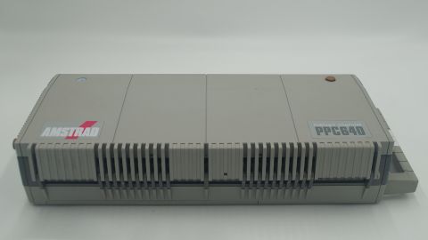 Closed for carrying
 -
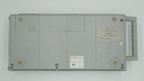 Underside, with the battery cover and PPC640D rating label
 -
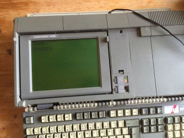 At switch-on, asking for the time and date and new batteries


Related pages
[edit | edit source]- Amstrad PC1512 · Amstrad PC1640
- Battery Refurbishment · Battery Explosion, Capacitor or Corrosion Damage
References
[edit | edit source]- ↑ Vintage Laptops Museum, "Amstrad Portable PPC 640". Retrieved 2026-10-02. Gives the price as US$1,099 (1987), 16 KB ROM and the 300/1200/2400 bps modem.
- ↑ 2.00 2.01 2.02 2.03 2.04 2.05 2.06 2.07 2.08 2.09 2.10 2.11 2.12 2.13 2.14 2.15 2.16 2.17 Amstrad plc, PPC512S/512D, PPC640S/640D Personal Portable Computer Service Manual. Hosted as File:Amstrad PPC 512 PPC 640 Service Manual.pdf, described at Amstrad PPC 512 / PPC 640 Service Manual. Technical specification and notes to service engineers p. 2; alignment p. 14; cabinet parts list p. 16; power supply schematic p. 26; modem schematics pp. 27–28; electrical parts list pp. 29–31.
- ↑ 3.0 3.1 3.2 3.3 3.4 Wikipedia, "Amstrad PPC". Retrieved 2026-10-02. Release in 1987 as Amstrad's first portable PC compatibles, developed from the PC1512 and PC1640; PPC Organizer and Mirror II; the 1988 PC20 and Sinclair PC200 based on the PPC design.
- ↑ 4.00 4.01 4.02 4.03 4.04 4.05 4.06 4.07 4.08 4.09 4.10 4.11 4.12 4.13 4.14 Amstrad Consumer Electronics plc, Amstrad PPC Technical Reference Manual (Bill Weidenauer, 1987), transcribed by John Elliott at seasip.info. Retrieved 2026-10-02. Preface; section 1 (hardware): 1.1 CPU, 1.2 memory, 1.9 real time clock, 1.10.3 option links, 1.12 floppy disc controller, 1.13 serial port, 1.16 modem, 1.18 expansion connectors and power requirements, 1.19 video connector, 1.20 power connectors, 1.21 switch settings; section 2 (firmware): 2.2 power-up self tests, 2.6 ROS messages.
- ↑ 5.0 5.1 5.2 Ewart Stronach, "Amstrad's PPC 512 and PPC 640 Portables", Your Computer (Australia), July 1988, pp. 62–64. Scan at archive.org. Retrieved 2026-10-02. The controls and ports, the "Please wait" start-up and the V1.8 sign-on, the clock running from the main batteries, and the nylon carry bag.
- ↑ CPU-World, "NEC V30 processor family". Retrieved 2026-10-01. Lists the Sony CXQ70116P-8 among V30 parts.
- ↑ 7.0 7.1 MCbx, "Amstrad PPC512", oldcomputer.info. Retrieved 2026-10-02. Disassembly, the 512 KB to 640 KB upgrade, the expansion box, the video and monitor power pinouts, the DIP switches and the option links LK1–LK7.
- ↑ 8.00 8.01 8.02 8.03 8.04 8.05 8.06 8.07 8.08 8.09 Amstrad plc, The Amstrad Portable PPC 512/640 User Instructions (US edition, first edition 1988). Hosted as File:Amstrad PPC 512 PPC 640 User Instructions.pdf, described at Amstrad PPC 512 / PPC 640 User Instructions. Power sources (introduction); inserting the batteries p. 9; configuration switches pp. 10–11; switching on pp. 13–14; LCD toggles p. 17; switching off p. 43; cleaning p. 50; external monitor pp. 317–318; troubleshooting pp. 327–339; PC2000 modem p. 236.