

Atari 130XE
.jpg) | |
| Atari 130XE home computer | |
| Specifications | |
|---|---|
| Manufacturer | Atari Corporation |
| Type | Home computer |
| Released | 1985 (announced at the Winter CES, January 1985) |
| CPU | MOS Technology 6502C @ 1.79 MHz (NTSC) / 1.77 MHz (PAL) |
| Memory | 128 KB RAM (64 KB main + 64 KB bank-switched); 24 KB ROM |
| Storage | Cassette (410/1010) or 5.25" floppy disk drive (1050/XF551) over SIO; ROM cartridge |
| Display | 40 x 24 text, up to 320 x 192 pixels |
| Sound | POKEY: four audio channels |
| OS / Firmware | Atari XE Operating System; Atari BASIC Rev. C in ROM |
| Predecessor | Atari 800XL |
| Successor | Atari XE Game System |
| Model no. | 130XE |
The Atari 130XE is the 128 KB member of Atari Corporation's XE range. It was announced alongside the Atari 65XE at the Winter Consumer Electronics Show in January 1985 - unpriced at the time - and is the most capable standard-production machine in the Atari 8-bit line.[1]
Atari's own field service manual for the machine is the source for the hardware detail below; it carries the schematics and silkscreens for all seven XE board assemblies, the chip pin assignments, the external power supply schematic and every connector pinout.[2]
Architecture and processor
[edit | edit source]The 130XE uses the 6502C at 1.79 MHz (NTSC) or 1.77 MHz (PAL), with the sixteen-line address bus giving the processor direct access to 64 KB and the eight-line data bus carrying data between the functional modules.[2] The board carries the CPU, ANTIC, GTIA, POKEY, the PIA, FREDDIE, RAM and the operating-system ROM.[2]
- ANTIC - display processor; also controls bus access and RAM refresh
- GTIA - generates colour and luminance from ANTIC's display bit stream
- POKEY - audio, SIO control, controller scan and keyboard scan
- PIA - general purpose I/O; also carries the bank-switching control bits
- FREDDIE - memory controller; also generates the clock signal to the CPU, from the
14 MHz master oscillator
- MMU1 (C061618) and MMU2 (C025953) - address decoding and bank selection[2]
The master oscillator is 14.31818 MHz (NTSC) or 14.187576 MHz (PAL).[2]
The memory management circuitry is a programmable array logic device plus a 3-to-8 decoder, taking address lines A8-A15 and control signals such as ROM enable (from the PIA) and refresh, and producing the GTIA select at $D0xx, the expansion select at $D1xx, the POKEY select at $D2xx, the PIA select at $D3xx, the cartridge selects at $D5xx, and the operating-system ROM and RAM selects.[2]
Memory
[edit | edit source]RAM is 128 KB, organised as sixteen 64K x 1 devices or four 64K x 4 devices, two per data line, depending on the board assembly.[2] ROM is 24 KB: a 16K x 8 operating system ROM plus 8 KB of Atari BASIC Rev. C. In the self test the ROM appears as two 8 KB bars.[2]
Bank switching
[edit | edit source]The extra 64 KB is reached through a 16 KB access window at $4000-$7FFF, controlled by four previously unused bits in the PIA registers at $D300. Two of the bits select which of the four 16 KB pages of the second bank appears in the window; the other two decide who sees it - the Video (ANTIC) Bank Enable and the CPU Bank Enable. That gives four modes:[3]
| Mode | CPU sees | ANTIC sees |
|---|---|---|
| Compatibility | Main bank | Main bank |
| CPU extended RAM | A page of the second bank, at $4000-$7FFF | Main bank |
| Video extended RAM | Main bank | A page of the second bank |
| Extended RAM | A page of the second bank | The same page of the second bank |
No synchronisation of bank addressing with display activity is needed by the programmer.[3] In practice the extended memory is most often used as a RAM disk under Atari DOS 2.5 and later disk operating systems; the field service manual notes that 48 KB is directly available and more is accessible under DOS 2.5.[2]
Two operating-system ROM part numbers are documented, C061598 and C300717. A board fitted with C300717 shows four extra bars in the self-test memory screen, one for each 16 KB extended bank.[2]
Display, video output and sound
[edit | edit source]Video is produced by ANTIC and GTIA: text up to 40 x 24, bitmap modes up to 320 x 192 pixels, four players and four missiles with collision detection, programmable display lists and hardware fine scrolling.
The 5-pin DIN monitor jack carries pin 1 monochrome (luminance) video, pin 2 ground, pin 3 audio, pin 4 composite video and pin 5 colour (chrominance).[2] RF output is via a built-in modulator on channel 2 or 3, 1-2 mV into 75 ohms, with the audio sound carrier 5.5 MHz above the video carrier.[2]
Input, output and expansion
[edit | edit source]- Cartridge slot - 30-pin edge connector. Pin 13 of the numbered row is Vcc +5 V.[2]
- Expansion connector (ECI) - a 14-pin edge connector behind the cartridge slot:
 A not connected, B interrupt request, C HALT from ANTIC, D-F address lines A13-A15, H ground;
 1 external select, 2 reset, 3 $D1xx I/O page select, 4 MPD from the MMU, 5 audio input,
 6 memory refresh, 7 Vcc +5 V.[2] Atari described it as providing equivalent architectural
 functionality to the XL's Parallel Bus Interface, without claiming physical
 equivalence.[3]
- SIO port - 13-pin, maximum 19.2 kbaud. Pin 10 is ready (computer on), pin 11 audio
in at 175 mV, and pin 12 is not used.[2]
- Two controller jacks - 9-pin D-type; pin 7 +5 V, pin 8 ground.[2]
- Monitor jack, RF output and power jack on the rear.
 | The SIO port carries no supply rail on the 130XE. Pin 10 is a ready signal and
pin 12 is unused; there is no +5 V on pin 10 and no +12 V on pin 12 to test.[2] |
Power
[edit | edit source]The 130XE takes +5 V DC at the power jack. The jack, the power switch and the filters are on the motherboard; the external brick contains the step-down transformer (115 V or 230 V AC in, 9 V AC out), the bridge rectifier, an LM78S05 regulator, a 4700 uF reservoir capacitor and a 100 uF output capacitor. Atari rates the output at 5 V +/-5%, 1.5 A maximum.[2] The machine's own stated requirement is 1.2 A at 5 V DC, higher than the 65XE because of the extra memory.[3]
There is no rectifier, bridge or on-board regulator anywhere on the 130XE motherboard.
Keyboard and self test
[edit | edit source]A full-stroke 62-key alphanumeric keyboard with special characters and controls, a space bar and five function keys, connected to the board by a 24-conductor foil cable.[2] From left to right the function keys are HELP, START, SELECT, OPTION and RESET. Holding OPTION while switching on disconnects the internal BASIC and, with no active floppy drive, runs the self test; HELP ends a looping test.[2]
Atari's production test cartridge adds a numbered diagnostic error-code table - error 01 and 02 for ANTIC sync and vertical-blank faults, 04-10 for RAM and address decoding, 11 and 12 for POKEY, 34-39 for the serial and controller ports. The full table is reproduced on the Atari 130XE Troubleshooting Guide.[2]
Board assemblies
[edit | edit source]| Assembly | RAM | Notes |
|---|---|---|
| CO70065 / CO70067 | 16 x 4164 (64K x 1) | Schematic figure 2-1, silkscreen figure 2-2[2] |
| CO70050 / CO70052 Rev. 2 | 16 x 4164 | SECAM version; schematic figure 2-3, silkscreen figure 2-4[2] |
| C103579-001 / CA200519 | 4 x 4464 (64K x 4) | Later assembly; schematic figure 2-5, silkscreen figure 2-6[2] |
Atari's manual warns that minor design variations occur with production date.[2]
Gallery
[edit | edit source]-
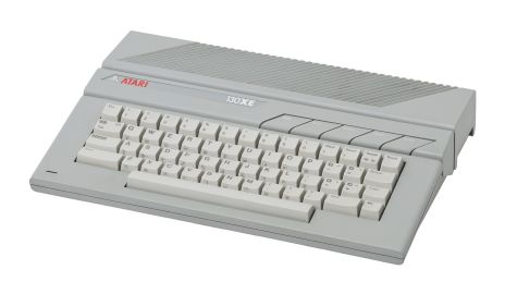 Atari 130XE
 -
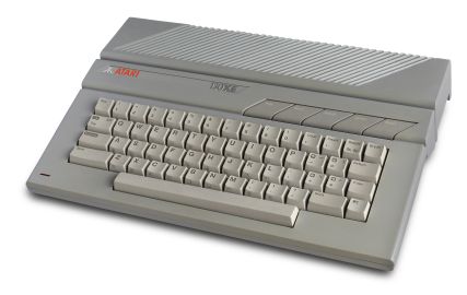 Atari 130XE

Service documentation
[edit | edit source]| Field service manual | Parts list and production test |
|---|---|
| File:Atari 130XE Field Service Manual.pdf | File:Atari 130XE Parts List and Production Test Instructions.pdf |
Also available as pages: Atari 130XE Field Service Manual, Atari 130XE Parts List and Production Test Instructions and Sams Computerfacts Atari 130XE.
Related pages
[edit | edit source]- Atari 130XE General Maintenance
- Atari 130XE Troubleshooting Guide
- Atari 130XE Capacitor Replacement Guide
- Atari 65XE
- Atari 800XE
- Atari XE Game System
References
[edit | edit source]- ↑ Tim Onosko and John J. Anderson, "Atari strikes back", Creative Computing Vol. 11 No. 3 (March 1985), p. 59, reproduced at atarimagazines.com. Contemporary report of the Winter CES 1985 line-up, written from briefings by Atari marketing manager Brian Kerr; source for the 65XE, 65XEM and XEP prices and the AMY specification quoted here.
- ↑ 2.00 2.01 2.02 2.03 2.04 2.05 2.06 2.07 2.08 2.09 2.10 2.11 2.12 2.13 2.14 2.15 2.16 2.17 2.18 2.19 2.20 2.21 2.22 2.23 2.24 Atari, 130XE Personal Computer Field Service Manual. Section 1 (theory of operation, chip pin assignments, external power supply schematic and rating, connector pinouts), Section 2 (schematics and silkscreens for all seven XE board assemblies), Section 3 (self test and production-test diagnostic error codes). Despite its title it covers the 65XE, the 800XE and the XE Game System as well. Hosted on this wiki: File:Atari 130XE Field Service Manual.pdf.
- ↑ 3.0 3.1 3.2 3.3 Jack Powell, "130XE: How Atari's New 8-Bit Does It", Antic Vol. 4 No. 3 (July 1985), reproduced at atarimagazines.com. Atari's first published specification for the 130XE: bank-switching modes, the Enhanced Cartridge Interface signal list, and the 1.2 A at 5 V DC supply requirement.