

IBM PS/2 Model 25: Difference between revisions
P4 verification: remove the now-duplicated manual link bullet (superseded by the fuller documentation line) |
|||
| (4 intermediate revisions by the same user not shown) | |||
| Line 1: | Line 1: | ||
{{Infobox computer | {{Infobox computer | ||
| name = IBM Personal System/2 Model 25 | | name = IBM Personal System/2 Model 25 | ||
| logo = [[File:IBM PS2 Model 25 8086 badge.svg|150px]] | |||
| image = [[File:IBM PS2 Model 25.jpg|260px]] | | image = [[File:IBM PS2 Model 25.jpg|260px]] | ||
| caption = IBM PS/2 Model 25 (8525) | | caption = IBM PS/2 Model 25 (8525) | ||
| Line 6: | Line 7: | ||
| manufacturer = IBM | | manufacturer = IBM | ||
| type = All-in-one personal computer | | type = All-in-one personal computer | ||
| release date = August | | release date = 4 August 1987 (Model 25, 8086); May 1990 (Model 25 286); April 1992 (Model 25 SX) | ||
| discontinued = November | | discontinued = 17 November 1992 (Model 25 286) | ||
| cpu = Intel 8086 @ 8 MHz | | cpu = Intel 8086-2 @ 8 MHz, 0 wait states / Intel 80286 @ 10 MHz, 1 wait state / Intel 386SX @ 16 MHz | ||
| memory = 512 | | memory = 512–640 KB (8086); 512 KB–4 MB on board (286); up to 12 MB (SX, non-K planars) | ||
| storage = One or two 3.5" | | storage = One or two 3.5" diskette drives; optional IBM fixed disk drive with its controller on the drive; 40-pin IDE on the SX | ||
| display = Integrated 12" CRT | | display = Integrated 12" CRT, monochrome or colour. MCGA (8086), VGA (286), IBM SVGA (SX) | ||
| sound = PC speaker; | | sound = PC speaker; earphone jack | ||
| dimensions = 382 | | dimensions = 382 × 320 × 375 mm | ||
| weight = 12.7 kg | | weight = 12.7 kg monochrome; 16.8 kg colour | ||
| os = IBM PC DOS 3.3 | | os = IBM PC DOS 3.3 and later; OS/2 1.x on the 286 | ||
| predecessor = | | predecessor = entry-level PS/2, replacing the [[IBM PC (5150)]] and [[IBM PC XT (5160)|XT]] in the range | ||
| successor = IBM PS/1 | | successor = IBM PS/1; IBM PS/ValuePoint | ||
| model = 8525 | | model = 8525 | ||
}} | }} | ||
The '''IBM Personal System/2 Model 25''' (machine type '''8525''') is the | The '''IBM Personal System/2 Model 25''' (machine type '''8525''') is the entry point of the PS/2 range, announced on 4 August 1987, four months after IBM unveiled the rest of the line. It is the only PS/2 with an '''integrated CRT''' in an all-in-one case, and — like the [[IBM PS/2 Model 30|Model 30]] — it uses '''ISA''' expansion rather than Micro Channel. | ||
Three generations were sold: | |||
* '''Model 25''' | * '''Model 25''' — Intel 8086-2 at 8 MHz, MCGA video, 8-bit ISA, from August 1987. | ||
* '''Model 25 286''' | * '''Model 25 286''' — 80286 at 10 MHz, VGA, 16-bit ISA, from May 1990 to November 1992. | ||
* '''Model 25 SX''' | * '''Model 25 SX''' — 386SX, IBM SVGA, 16-bit ISA, sold to the K–12 education market from April 1992. | ||
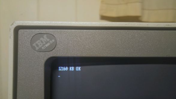
All three | All three share the all-in-one chassis and the 12-inch display assembly, and all three take drive power and data through connectors on the planar rather than through Molex leads. | ||
== | == Submodels == | ||
IBM | <templatestyles src="Template:StyledTable/styles.css" /> | ||
{| class="wikitable styled-table" style="width:95%; text-align:center;" | |||
|+'''Selected IBM PS/2 Model 25 submodels''' | |||
! Submodel !! CPU !! Bus !! RAM (max on board) !! Diskette !! Fixed disk !! Display !! Notes | |||
|- | |||
| 8525-001 || 8086-2, 8 MHz || ISA 8-bit || 512 KB (640 KB) || 1 × 720 KB || none || 12" monochrome || US$2,095 list | |||
|- | |||
| 8525-004 || 8086-2, 8 MHz || ISA 8-bit || 512 KB (640 KB) || 1 × 720 KB || none || 12" colour || US$2,595 list | |||
|- | |||
| 8525-G01 / G04 || 8086-2, 8 MHz || ISA 8-bit || 512 KB (640 KB) || 1 × 720 KB || none || mono / colour || Enhanced 101-key keyboard | |||
|- | |||
| 8525-C02 / C05 || 8086-2, 8 MHz || ISA 8-bit || 640 KB || 2 × 720 KB || none || mono / colour || Collegiate kit | |||
|- | |||
| 8525-L01 / L04 || 8086-2, 8 MHz || ISA 8-bit || 512 KB (640 KB) || 1 × 720 KB || none || mono / colour || LS, with Token Ring | |||
|- | |||
| 8525-006 / G06 || 80286, 10 MHz || ISA 16-bit || 512 KB (4 MB) || 1 × 1.44 MB || none || 12" VGA colour || | |||
|- | |||
| 8525-036 / G36 || 80286, 10 MHz || ISA 16-bit || 1 MB (4 MB) || 1 × 1.44 MB || 30 MB || 12" VGA colour || | |||
|- | |||
| 8525-K00 / K01 || 386SX || ISA 16-bit || up to 12 MB || 1 × 1.44 MB || IDE (optional) || 12" SVGA colour || School market; K01 adds Ethernet | |||
|- | |||
| 8525-L02 || 386SX || ISA 16-bit || up to 12 MB || 1 × 1.44 MB || IDE (optional) || 12" SVGA colour || Adds Token Ring | |||
|} | |||
Prices, weights and dimensions are IBM's own.<ref name="qref25">IBM Canada Ltd Quick Reference, "IBM PS/2 Model 25 (8525)", mirrored at [https://www.ardent-tool.com/qtechinfo/8525.html ardent-tool.com]. IBM-supplied product data: the announce date, the US$2,095 (8525-001) and US$2,595 (8525-004) list prices, the microprocessor and clock, the bus, the ports, the DIP and MMK 100–150 ns parity memory, the power-supply ratings, the weights (12.7 kg monochrome, 16.8 kg colour), the dimensions (382 × 320 × 375 mm) and the MCGA colour summing to 64 grey shades in BIOS on a monochrome display. Note that this document rounds the colour machine's supply to 115 W where IBM's own ''Technical Reference'' gives 113 W.</ref><ref name="ann187148">IBM Announcement Letter 187-148, ''IBM 8525, PS/2 Model 25''. Gives the 12-inch colour or monochrome analog display, MCGA with a 64 KB display buffer, the 8525-001 (monochrome) and 8525-004 (colour) minimum configurations with 512 KB RAM and one 720 KB diskette drive, the 8525-G01 and G04 Enhanced Keyboard variants, the universal power supply with a rear switch for 90–137 Vac or 180–259 Vac at 50–60 Hz, and the system bolt-down capability.</ref> The 286 and SX machine types are listed in the ardent-tool planar pages.<ref name="at8525planar286">Louis Ohland, Tomáš Slavotínek ''et al.'', "8525-286 Planar", Ardent Tool of Capitalism, https://www.ardent-tool.com/8525/Planar_286.html. Gives the 8525-286 planar designator map (FRU P/N 64F0178, P/N 37F6675; VL82CPCAT-QC chipset at ZM2–ZM6, VL16C451 at ZM9, DS1287 RTC/CMOS at ZM35, 8042 keyboard controller at ZM33, 286-10 CPU socket at ZM36, F1 combined keyboard/mouse fuse, J7 and J14 power-supply connectors, J13 password-override connector, J15 earphone connector), the earphone connector board part numbers, the memory expansion starting-address table, and the machine types 8525-006, G06, 036 and G36.</ref><ref name="at8525sx">Louis Ohland, William R. Walsh, Tomáš Slavotínek ''et al.'', "8525 SX Planar", Ardent Tool of Capitalism, https://www.ardent-tool.com/8525/Planar_SX.html. Gives the Model 25 SX "K" and "L" planar designator maps (FRU P/N 87F4769; B1 CR2032 battery, U2 i386SX, U8 VL82C304, U9 VL82C305, U10 Intel i8042 keyboard controller, U25 82077AA diskette controller, U26 ROM BIOS 87F4794, U42 IBM SVGA 84F7985, J2 power-on password clear, J10 40-pin IDE, J11 40-pin diskette, J12 and J13 power, J14 4-pin Molex for hard-disk power, Y1 32.768 kHz RTC crystal), the machine types 8525-K00, K01 and L02, the flipped riser slot for an Ethernet or Token Ring adapter, the statement that the monitor assembly is identical to every other Model 25, and the 16 versus 20 MHz CPU question.</ref> | |||
== Architecture == | |||
=== Model 25 (8086) planar === | |||
= | Three planars exist — Type 1 (P/N 00F2073), Type 2 (FRU P/N 96F7390, P/N 64F0738) and a Japanese board (P/N 78X8943) built by Panasonic/Matsushita. '''The PCB layouts differ drastically, but the reference designators are largely consistent across all of them''', and across the 8086-based [[IBM PS/2 Model 30|Model 30]] planars as well.<ref name="at8525planar">Louis Ohland, William R. Walsh, Tomáš Slavotínek ''et al.'', "8525 Planar", Ardent Tool of Capitalism, https://www.ardent-tool.com/8525/Planar.html. Gives the Model 25 Type 1 (P/N 00F2073), Type 2 (FRU P/N 96F7390, P/N 64F0738) and Japanese (P/N 78X8943) planar designator maps; the riser card P/N 78X9031 and its contents; the note that reference designators are largely consistent across all 8086-based Model 25 and Model 30 planars; the warning that the Model 25 8086 does not use the same power connector as the Model 30 8086; and William Walsh's account of PS/2 diskette drives ("you might as well plan on replacing every one of the surface mounted electrolytic capacitors on the drive's circuit board, and almost certainly cleaning up the corrosive mess left behind") and of undocumented 1.44 MB support with Sony drives.</ref> | ||
{| class="wikitable styled-table" style="width:95%;" | |||
|+'''Model 25 8086 planar — principal designators''' | |||
{| class="wikitable styled-table" style="width: | ! Designator !! Device | ||
|+''' | |- | ||
! | | U10 || Intel 8086-2 CPU, 8 MHz | ||
|- | |||
| U13 || Intel 8087 coprocessor socket | |||
|- | |||
| U8 || Intel P8253-5 programmable interval timer | |||
|- | |||
| U9 / U11 / U12 / U14 / U15 || IBM gate arrays: 72X8203, 72X8300 (MCGA memory controller), 72X8205 (MCGA video formatter), 72X8206 and 72X8202 | |||
|- | |||
| U5 || Inmos IMSG171P RAMDAC | |||
|- | |||
| U6, U7 || HM53461P 64K×4 DRAM (MCGA video memory) | |||
|- | |||
| U38 || Sony CXK5864BM-12L 8K×8 static RAM (MCGA) | |||
|- | |- | ||
| | | U16, U22, U34, U35 || NEC D4164C-10 DRAM | ||
|- | |- | ||
| | | ZM1, ZM2 || OKI MSM3764A-15 DRAM | ||
|- | |- | ||
| | | U17, U20 || ROM BIOS (two devices) | ||
|- | |- | ||
| | | U18 || NEC uPD765AC-2 diskette controller | ||
|- | |- | ||
| | | U19 || 8237A DMA controller | ||
|- | |- | ||
| | | U27 || NS8250AV UART | ||
|- | |- | ||
| | | U2, U3 / U4 || DS1489AN line receivers / NS1488N line driver | ||
|- | |- | ||
| | | F1 / F2 || Mouse and keyboard fuses (combined into F1 on the Type 2 planar) | ||
|- | |- | ||
| | | J1 / J2 || Mouse / keyboard connectors | ||
|- | |- | ||
| | | J9 || Dual 30-pin SIMM socket | ||
|- | |- | ||
| | | J11 || '''44-pin fixed-disk connector''' | ||
|- | |- | ||
| | | J12 || 40-pin diskette connector | ||
|- | |- | ||
| | | J7 || Power connector | ||
|- | |- | ||
| | | ZM3 || Earphone connector | ||
|- | |- | ||
| | | Y1 / Y2 / Y3 || 14.31818 MHz / 25.175 MHz / 48.0 MHz oscillators | ||
|} | |} | ||
'''Note what is not on that list: no real-time clock and no 32.768 kHz crystal.''' The 8086 Model 25 has no hardware clock and no battery. Date and time are set at each boot, and there is nothing here to replace.<ref name="at8525planar" /> | |||
The riser card (P/N 78X9031, "SYNTEC") carries '''two 8-bit ISA slots''' and no components other than a resistor pack — so there is no battery on the riser either, unlike the 8086 Model 30.<ref name="at8525planar" /> | |||
The Model 25 | '''The Model 25 8086 does not use the same power connector as the Model 30 8086''', so although the two boards share a designator scheme they are not interchangeable machines.<ref name="at8525planar" /> | ||
=== Model 25 286 planar === | === Model 25 286 planar === | ||
FRU P/N 64F0178 (P/N 37F6675), built around the '''VLSI VL82CPCAT-QC''' ("PC/AT-compatible") chipset. It is very similar to the single-ROM Model 30 286 planar.<ref name="at8525planar286" /> | |||
* '''ZM36''' — 286-10 CPU socket; '''ZM1''' — 287-10 coprocessor socket. | |||
* '''ZM2–ZM6''' — VL82C100 peripheral controller, VL82C102A memory controller, VL82C103A address buffer, VL82C104 data buffer, VL82C101B system controller. | |||
* ''' | * '''ZM9''' — VL16C451 parallel port and UART. | ||
* ''' | * '''ZM14''' — 27F4094 "DISKGA" disk/diskette gate array. | ||
* ''' | * '''ZM18''' — 15F6864 VGA controller, with '''ZM23''' IMSG171P-35 RAMDAC and eight 64K×4 DRAMs at ZM47–ZM54. | ||
* | * '''ZM19''' — NEC uPD765BC diskette controller. | ||
* | * '''ZM33''' — Intel 8042 keyboard controller. | ||
* '''ZM35''' — '''Dallas DS1287''' RTC/CMOS module, with the lithium cell sealed inside it. | |||
* '''ZM46''' — BIOS ROM on later boards (earlier boards use two devices at ZM11/ZM12). | |||
* '''J9 / J10''' — two 30-pin SIMM sockets, 100–150 ns with parity; 512 KB minimum, 4 MB maximum on the board, 16 MB using adapter cards. | |||
* '''J13''' — password-override connector. '''J7 and J14''' — power. '''F1''' — combined keyboard/mouse fuse. | |||
=== Model 25 SX planar === | === Model 25 SX planar === | ||
FRU P/N 87F4769, in "K" and "L" variants.<ref name="at8525sx" /> | |||
* '''U2''' — Intel i386SX. Most machines have a 20 MHz part '''underclocked to 16 MHz''' by the 32.000 MHz oscillator at OS1; some have a genuine 16 MHz chip. | |||
* '''U5''' — 80387SX-16 socket. | |||
* '''U8 / U9''' — VLSI VL82C304-QC and VL82C305-FC (84F9161). | |||
* '''U10''' — '''Intel 8042 keyboard controller'''. This is worth knowing: on this board U10 is not memory or an RTC. | |||
* '''U25''' — Intel 82077AA diskette controller. '''U26''' — ROM BIOS 87F4794. | |||
* '''U42''' — IBM SVGA 84F7985, with TC511665BZ-80 video RAM at U43/U44/U51/U54 and an IMSG171P RAMDAC at U45. | |||
* '''U34, U36''' (and, on non-"K" planars, U11/U13/U33/U35/U48/U49) — HM514900JP8 512K×9 DRAM. | |||
* '''J6''' — 72-pin SIMM socket ("MEM 3"). '''J4''' is a set of pads for a second socket that IBM never fitted; attempts to add one have failed with memory errors. | |||
* '''J10''' — 40-pin '''IDE''' connector. '''J14''' — 4-pin Molex for hard-disk power. '''J2''' — power-on password clear. | |||
* '''B1''' — '''CR2032''' coin cell backing the clock, which is inside the VLSI chipset and timed by the Y1 32.768 kHz crystal. '''It is not a Dallas module.''' | |||
== | == Storage == | ||
=== Diskette === | |||
=== | Drive power and data are carried on a single cable from the planar's 40-pin diskette connector; there is no separate Molex lead.<ref name="tr25">IBM, ''IBM Personal System/2 Model 25 Technical Reference'', June 1987. [[:File:IBM PS2 Model 25 Technical Reference Jun87.pdf]]. Section 3 "Power Supply", pages 3-3 to 3-6, gives the 113 W colour and 90 W monochrome ratings, the rails supplied to the system board and to the display assembly, the mechanical voltage switch on the rear, the Vac input requirements, the Vdc output regulation and ripple, the output protection sense levels, the power-good characteristics and the J7 pin assignments. Section 1 gives the earphone connector specification and the 40-pin diskette and 44-pin fixed-disk connector pin assignments, and pages 1-126 and 1-127 give the system board connector location drawings.</ref><ref name="dosdays25">"IBM PS/2 Model 25", DOS Days, https://www.dosdays.co.uk/computers/IBM%20PS2%20Model%2025/ibm_ps2_model_25.php. Source for the single power-and-data cable with no Molex connectors, the absence of a dust shutter and the electrolyte corrosion on drive logic boards, the warning that a Model 30 supply is not a drop-in for a Model 25 because the planar connectors differ, the expansion slot counts for the three generations, and the Sony 1.44 MB drive compatibility note.</ref> Drives are ALPS, Mitsubishi, Sony or YE-Data. The 8086 Model 25 shipped only with 720 KB drives, but has '''undocumented''' 1.44 MB support — in practice only with Sony drives, and later planars are more tolerant than early ones.<ref name="at8525planar" /> | ||
PS/2 3.5-inch drives are '''direct drive'''. The Mitsubishi MF355C specification states that the spindle is turned directly by a DC brushless motor at 300 rpm; there is no belt in these drives.<ref name="mf355c">Mitsubishi Electric, ''3.5 inch Flexible Disk Drive Standard Specifications, MF355C'', document UGD-0527A, February 1987. [[:File:Mitsubishi MF355C 3.5 inch Diskette Drive Specifications (UGD-0527A, Feb 1987).pdf]]. Section 3 states that the disk rotation mechanism uses a DC brushless direct-drive motor to rotate the spindle directly at 300 rpm; the drive has no belt.</ref> What does fail is the surface-mount electrolytics on the drive's logic board, and the corrosion they leave behind.<ref name="ibmfiles">[https://www.ibmfiles.com/pages/ps2capacitors.htm PS/2 Surface Mount Capacitors], ibmfiles.com. Community teardown source; documents surface-mount electrolytic failure and pad corrosion on PS/2 Mitsubishi diskette drives and on the DBA hard-drive logic boards, and the technique of fitting through-hole parts to the surface-mount pads.</ref> | |||
=== | === Fixed disk === | ||
'''The Model 25 does not have an ST-506 controller on the planar.''' IBM's ''Technical Reference'' describes the fixed-disk connector as "a dedicated I/O channel for the connection of the IBM Personal System/2 20MB Fixed Disk Drive and controller, or similar attachment": the signals are ordinary I/O-channel signals plus −DISK CS (decoded at hex 032x), −Disk Installed and address lines A0–A2 to select a register '''within the controller'''.<ref name="tr25" /> In other words the controller travels with the drive, on IBM's own 44-pin connector.<ref name="at8525planar" /> | |||
= | The Model 25 286 submodels 8525-036 and G36 shipped with a 30 MB drive on the same planar connector. The Model 25 SX is the only Model 25 with a conventional '''40-pin IDE''' interface, at J10.<ref name="at8525sx" /> | ||
There is no standard hard-disk power connector on the 8086 machine; adding one is a known modification.<ref name="at8525planar" /> | |||
== Display == | == Display == | ||
The Model 25 | The 8086 Model 25 uses '''MCGA''', integrated on the planar with a '''64 KB display buffer'''.<ref name="ann187148" /> The palette is a '''256-entry, 18-bit''' table driving three 6-bit DACs — so 256 simultaneous colours out of 262,144.<ref name="tr25" /> On a monochrome machine the BIOS sums colours to 64 shades of grey.<ref name="qref25" /> | ||
{| class="wikitable styled-table" style="width: | {| class="wikitable styled-table" style="width:90%; text-align:center;" | ||
|+'''MCGA video modes | |+'''MCGA video modes''' | ||
! Mode !! Resolution !! Colours | ! Mode !! Resolution !! Colours !! Notes | ||
|- | |- | ||
| 0 / 1 || 40 | | 0 / 1 || 40 × 25 text || 16 || CGA-compatible | ||
|- | |- | ||
| 2 / 3 || 80 | | 2 / 3 || 80 × 25 text || 16 || CGA-compatible | ||
|- | |- | ||
| 4 / 5 || 320 | | 4 / 5 || 320 × 200 || 4 || CGA-compatible | ||
|- | |- | ||
| 6 || 640 | | 6 || 640 × 200 || 2 || CGA-compatible | ||
|- | |- | ||
| | | hex 11 || 640 × 480 || 2 || MCGA-specific | ||
|- | |- | ||
| | | hex 13 || 320 × 200 || 256 || MCGA-specific | ||
|} | |} | ||
MCGA is '''analogue only'''. It will not drive a TTL digital CGA or MDA monitor. EGA modes are not supported.<ref name="at8525planar" /> | |||
The Model 25 286 and Model 25 SX | The Model 25 286 has VGA (15F6864 gate array), and the Model 25 SX has IBM's SVGA controller (84F7985) — the same part used on the 512 KB SVGA/A adapter and on the Model 40 SX planar.<ref name="at8525planar286" /><ref name="at8525sx" /> The display assembly itself is identical across every Model 25.<ref name="at8525sx" /> | ||
== Keyboard and Mouse == | == Keyboard and Mouse == | ||
The Model 25 | The Model 25 introduced the 6-pin Mini-DIN keyboard and pointing-device connectors that became the PS/2 standard. On the 8086 machine '''the two are genuinely interchangeable''': IBM's ''Technical Reference'' states that "the interface logic for the keyboard and the pointing device is the same, allowing the keyboard and pointing device to plug into either of the two 6-pin connectors at the rear of the system."<ref name="tr25" /> The interface is in the I/O support gate array, which also holds the chip-select logic and the interrupt controller.<ref name="tr25" /> The 286 and SX planars use a discrete '''8042''' instead.<ref name="at8525planar286" /><ref name="at8525sx" /> | ||
Each port is fuse-protected on the planar — F1 for the mouse and F2 for the keyboard on the Type 1 board, combined into F1 on the Type 2 and on the 286 and SX boards.<ref name="at8525planar" /><ref name="at8525planar286" /> A '''305''' at POST is a keyboard voltage error, and IBM's first suggested FRU is the port fuse.<ref name="aterr">"PS/2 Error Codes", Ardent Tool of Capitalism, https://www.ardent-tool.com/trouble/ps2error.html, with the error code listings at https://www.ardent-tool.com/trouble/error_02.html (160–199) and https://www.ardent-tool.com/trouble/error_04.html (300–999). Gives the beep codes, the 161/162/163/167/168 battery and clock cluster with IBM's FRU order and the lithium battery caution, the 301–307 keyboard cluster including 305 "keyboard voltage error" with the keyboard port fuse as first FRU, the diskette cluster including 604 "unsupported drive or cable" and 662/663 wrong drive and media type, the dead-system isolation procedure, and the warning that soft-booting the Reference Diskette can produce false errors.</ref> | |||
== Power Supply == | |||
The supply is '''inside the display assembly''' and feeds the system board, the display, the options and the keyboard.<ref name="tr25" /> | |||
== | * '''Colour machines: 113 W''', a single-phase, six-voltage-level supply. It delivers 7.0 A of +5 V, 1.7 A of +12 V, 100 mA of −5 V and 250 mA of −12 V to the system board, plus 450 mA of 115 V dc and 220 mA of +12 V dc to the display assembly.<ref name="tr25" /> | ||
* '''Monochrome machines: 90 W''', a single-phase, five-voltage-level supply. The system-board rails are identical; the display assembly instead gets 800 mA of +39 V dc.<ref name="tr25" /> | |||
* '''Model 25 286 and Model 25 SX: 124.5 W''', dual voltage with a switch on the rear.<ref name="ann190082">IBM Announcement Letter 190-082, ''IBM PS/2 Model 25 286 (8525-006, G06, 036, G36)''. Gives the 124.5 watt dual-voltage power supply with a switch on the rear, the 100–125 Vac and 200–240 Vac input ranges, the 654 BTU/hr figure and the 16.0 kg weight of the diskette-only models.</ref><ref name="ann192019">IBM Announcement Letter 192-019, ''IBM PS/2 Model 25 SX (8525-K00, K01, L02)''. Gives the 124.5 W power supply rating and DOS 5.0 as the shipped operating system.</ref> | |||
IBM's Canadian quick reference rounds the colour 8086 machine's supply to 115 W; the ''Technical Reference'' figure of '''113 W''' is the one to quote.<ref name="qref25" /><ref name="tr25" /> | |||
The system board and drives take about 4 A of +5 V, leaving roughly 3 A for the two expansion slots. −5 V exists for adapters; +12 V runs the drives; +12 V and −12 V drive the serial port's EIA line drivers.<ref name="tr25" /> | |||
{| class="wikitable styled-table" style="width:90%; text-align:center;" | |||
|+'''Model 25 — dc output and protection (IBM figures)''' | |||
! Rail !! Min load !! Max load !! Regulation !! Under-voltage sense | |||
|- | |||
| +5 Vdc || 1.5 A || 7.0 A || +5% to −3% || +3.2 V | |||
|- | |||
| −5 Vdc || 0.0 A || 0.11 A || +10% to −8% || −2.4 V | |||
|- | |||
| +12 Vdc || 0.12 A || 1.7 A || +5% to −3% || +10.5 V | |||
|- | |||
| −12 Vdc || 0.015 A || 0.25 A || +10% to −8% || −8.6 V | |||
|} | |||
Vac input is 115 V nominal (90–137 V, 2.0 A max) or 230 V nominal (180–265 V, 1.0 A max), selected by a mechanical switch and protected by an internal fuse. If a dc over-current or under-voltage condition exists, the supply shuts down until it is corrected.<ref name="tr25" /> The 'power good' signal is active at 2.4 to 5.25 Vdc with a turn-on delay of at least 100 ms and no more than 500 ms.<ref name="tr25" /> | |||
Power arrives at the planar on the 12-pin '''J7''' connector: pin 1 Power Good, pins 2 and 5–8 ground, pin 3 +12 V, pin 4 −12 V, pin 9 −5 V, pins 10–12 +5 V.<ref name="tr25" /> Measurement limits for a working machine are published for the same connector.<ref name="atpower">Louis Ohland, Tomáš Slavotínek ''et al.'', "8525 / 8530 Power", Ardent Tool of Capitalism, https://www.ardent-tool.com/8530/Power.html. Transcribes IBM's Hardware Maintenance Service data for the 8525 and 8530: the J7 connector measurement limits for the Models 25, 25 SX and 25-286, the minimum under-voltage sense levels, the power-good range and the dead-system isolation procedure, and the warning that the manually-switchable supply must be set before the cord is plugged in.</ref> | |||
'''A Model 30 supply is not a drop-in replacement.'''<ref name="dosdays25" /> | |||
== ROM BIOS and Reference Diskette == | |||
The PS/2 BIOS is in two layers: '''CBIOS''' for DOS compatibility and '''ABIOS''' for protected-mode OS/2. There is no built-in SETUP; configuration is done by booting the model-specific '''Reference Diskette''', which also carries Advanced Diagnostics (Ctrl-A from the main menu) and the backup utility. | |||
Cold | '''Reference Diskettes are model-specific.''' A Model 30 diskette will not configure a Model 25, and the 8086, 286 and SX machines each need their own. Cold-boot the Reference Diskette rather than warm-booting it: a soft boot can produce false errors, including a false report that a power-on password is set.<ref name="aterr" /> | ||
== General Maintenance == | == General Maintenance == | ||
CRT | Opening the machine, CRT safety, planar inspection, rail checks, RTC battery replacement on the 286 and SX and connector care are in [[IBM PS/2 Model 25 Maintenance Guide]]. | ||
== Troubleshooting == | == Troubleshooting == | ||
Beep codes, the numeric POST code list, dead-system isolation, Reference Diskette procedure and display diagnostics are in [[IBM PS/2 Model 25 Troubleshooting Guide]]. | |||
== Capacitor Replacement == | == Capacitor Replacement == | ||
Planar decoupling, the supply, the display assembly and the diskette drive logic board are in [[IBM PS/2 Model 25 Capacitor Replacement Guide]]. | |||
== Gallery == | == Gallery == | ||
<gallery mode="packed" heights="220"> | <gallery mode="packed" heights="220"> | ||
File:IBM PS2 Model 25 product photo.png|IBM PS/2 Model 25 | File:IBM PS2 Model 25 product photo.png|IBM PS/2 Model 25, early product photograph | ||
File:IBM PS2 Model 25 front.jpg| | File:IBM PS2 Model 25 front.jpg|Front view | ||
File:IBM PS2 Model 25 angle.jpg| | File:IBM PS2 Model 25 angle.jpg|Angled view | ||
File:IBM PS2 Model 25 SX.jpg| | File:IBM PS2 Model 25 SX.jpg|Model 25 SX, sold to schools | ||
File:IBM PS2 Model 25 8086 badge.svg| | File:IBM PS2 Model 25 8086 badge.svg|8086 front badge | ||
File:IBM PS2 Model 25 286 badge.svg| | File:IBM PS2 Model 25 286 badge.svg|Model 25 286 front badge | ||
</gallery> | </gallery> | ||
== | == References == | ||
<references /> | |||
== | == Related Pages == | ||
* [ | * [[IBM PS/2 Model 25 Maintenance Guide]] · [[IBM PS/2 Model 25 Troubleshooting Guide]] · [[IBM PS/2 Model 25 Capacitor Replacement Guide]] | ||
* [[IBM PS/2 Model 30]] — the desktop sibling | |||
* [[IBM PC XT (5160)]] · [[IBM PCjr]] | |||
* [ | * '''IBM documentation hosted here:''' [[IBM PS2 Model 25 Technical Reference (June 1987)]] · [[IBM Personal System 2 Hardware Maintenance Manual (S52G-9971-02, October 1994)]] | ||
* IBM | |||
{{Navbox-IBMComputers|state= | {{Navbox-IBMComputers|state=collapsed}} | ||
[[Category:IBM]] | [[Category:IBM]] | ||
Latest revision as of 00:20, 25 September 2026
 | |
 | |
| IBM PS/2 Model 25 (8525) | |
| Specifications | |
|---|---|
| Developer | IBM Entry Systems Division, Boca Raton |
| Manufacturer | IBM |
| Type | All-in-one personal computer |
| Released | 4 August 1987 (Model 25, 8086); May 1990 (Model 25 286); April 1992 (Model 25 SX) |
| Discontinued | 17 November 1992 (Model 25 286) |
| CPU | Intel 8086-2 @ 8 MHz, 0 wait states / Intel 80286 @ 10 MHz, 1 wait state / Intel 386SX @ 16 MHz |
| Memory | 512–640 KB (8086); 512 KB–4 MB on board (286); up to 12 MB (SX, non-K planars) |
| Storage | One or two 3.5" diskette drives; optional IBM fixed disk drive with its controller on the drive; 40-pin IDE on the SX |
| Display | Integrated 12" CRT, monochrome or colour. MCGA (8086), VGA (286), IBM SVGA (SX) |
| Sound | PC speaker; earphone jack |
| Dimensions | 382 × 320 × 375 mm |
| Weight | 12.7 kg monochrome; 16.8 kg colour |
| OS / Firmware | IBM PC DOS 3.3 and later; OS/2 1.x on the 286 |
| Predecessor | entry-level PS/2, replacing the IBM PC (5150) and XT in the range |
| Successor | IBM PS/1; IBM PS/ValuePoint |
| Model no. | 8525 |
The IBM Personal System/2 Model 25 (machine type 8525) is the entry point of the PS/2 range, announced on 4 August 1987, four months after IBM unveiled the rest of the line. It is the only PS/2 with an integrated CRT in an all-in-one case, and — like the Model 30 — it uses ISA expansion rather than Micro Channel.
Three generations were sold:
- Model 25 — Intel 8086-2 at 8 MHz, MCGA video, 8-bit ISA, from August 1987.
- Model 25 286 — 80286 at 10 MHz, VGA, 16-bit ISA, from May 1990 to November 1992.
- Model 25 SX — 386SX, IBM SVGA, 16-bit ISA, sold to the K–12 education market from April 1992.
All three share the all-in-one chassis and the 12-inch display assembly, and all three take drive power and data through connectors on the planar rather than through Molex leads.
Submodels
[edit | edit source]| Submodel | CPU | Bus | RAM (max on board) | Diskette | Fixed disk | Display | Notes |
|---|---|---|---|---|---|---|---|
| 8525-001 | 8086-2, 8 MHz | ISA 8-bit | 512 KB (640 KB) | 1 × 720 KB | none | 12" monochrome | US$2,095 list |
| 8525-004 | 8086-2, 8 MHz | ISA 8-bit | 512 KB (640 KB) | 1 × 720 KB | none | 12" colour | US$2,595 list |
| 8525-G01 / G04 | 8086-2, 8 MHz | ISA 8-bit | 512 KB (640 KB) | 1 × 720 KB | none | mono / colour | Enhanced 101-key keyboard |
| 8525-C02 / C05 | 8086-2, 8 MHz | ISA 8-bit | 640 KB | 2 × 720 KB | none | mono / colour | Collegiate kit |
| 8525-L01 / L04 | 8086-2, 8 MHz | ISA 8-bit | 512 KB (640 KB) | 1 × 720 KB | none | mono / colour | LS, with Token Ring |
| 8525-006 / G06 | 80286, 10 MHz | ISA 16-bit | 512 KB (4 MB) | 1 × 1.44 MB | none | 12" VGA colour | |
| 8525-036 / G36 | 80286, 10 MHz | ISA 16-bit | 1 MB (4 MB) | 1 × 1.44 MB | 30 MB | 12" VGA colour | |
| 8525-K00 / K01 | 386SX | ISA 16-bit | up to 12 MB | 1 × 1.44 MB | IDE (optional) | 12" SVGA colour | School market; K01 adds Ethernet |
| 8525-L02 | 386SX | ISA 16-bit | up to 12 MB | 1 × 1.44 MB | IDE (optional) | 12" SVGA colour | Adds Token Ring |
Prices, weights and dimensions are IBM's own.[1][2] The 286 and SX machine types are listed in the ardent-tool planar pages.[3][4]
Architecture
[edit | edit source]Model 25 (8086) planar
[edit | edit source]Three planars exist — Type 1 (P/N 00F2073), Type 2 (FRU P/N 96F7390, P/N 64F0738) and a Japanese board (P/N 78X8943) built by Panasonic/Matsushita. The PCB layouts differ drastically, but the reference designators are largely consistent across all of them, and across the 8086-based Model 30 planars as well.[5]
| Designator | Device |
|---|---|
| U10 | Intel 8086-2 CPU, 8 MHz |
| U13 | Intel 8087 coprocessor socket |
| U8 | Intel P8253-5 programmable interval timer |
| U9 / U11 / U12 / U14 / U15 | IBM gate arrays: 72X8203, 72X8300 (MCGA memory controller), 72X8205 (MCGA video formatter), 72X8206 and 72X8202 |
| U5 | Inmos IMSG171P RAMDAC |
| U6, U7 | HM53461P 64K×4 DRAM (MCGA video memory) |
| U38 | Sony CXK5864BM-12L 8K×8 static RAM (MCGA) |
| U16, U22, U34, U35 | NEC D4164C-10 DRAM |
| ZM1, ZM2 | OKI MSM3764A-15 DRAM |
| U17, U20 | ROM BIOS (two devices) |
| U18 | NEC uPD765AC-2 diskette controller |
| U19 | 8237A DMA controller |
| U27 | NS8250AV UART |
| U2, U3 / U4 | DS1489AN line receivers / NS1488N line driver |
| F1 / F2 | Mouse and keyboard fuses (combined into F1 on the Type 2 planar) |
| J1 / J2 | Mouse / keyboard connectors |
| J9 | Dual 30-pin SIMM socket |
| J11 | 44-pin fixed-disk connector |
| J12 | 40-pin diskette connector |
| J7 | Power connector |
| ZM3 | Earphone connector |
| Y1 / Y2 / Y3 | 14.31818 MHz / 25.175 MHz / 48.0 MHz oscillators |
Note what is not on that list: no real-time clock and no 32.768 kHz crystal. The 8086 Model 25 has no hardware clock and no battery. Date and time are set at each boot, and there is nothing here to replace.[5]
The riser card (P/N 78X9031, "SYNTEC") carries two 8-bit ISA slots and no components other than a resistor pack — so there is no battery on the riser either, unlike the 8086 Model 30.[5]
The Model 25 8086 does not use the same power connector as the Model 30 8086, so although the two boards share a designator scheme they are not interchangeable machines.[5]
Model 25 286 planar
[edit | edit source]FRU P/N 64F0178 (P/N 37F6675), built around the VLSI VL82CPCAT-QC ("PC/AT-compatible") chipset. It is very similar to the single-ROM Model 30 286 planar.[3]
- ZM36 — 286-10 CPU socket; ZM1 — 287-10 coprocessor socket.
- ZM2–ZM6 — VL82C100 peripheral controller, VL82C102A memory controller, VL82C103A address buffer, VL82C104 data buffer, VL82C101B system controller.
- ZM9 — VL16C451 parallel port and UART.
- ZM14 — 27F4094 "DISKGA" disk/diskette gate array.
- ZM18 — 15F6864 VGA controller, with ZM23 IMSG171P-35 RAMDAC and eight 64K×4 DRAMs at ZM47–ZM54.
- ZM19 — NEC uPD765BC diskette controller.
- ZM33 — Intel 8042 keyboard controller.
- ZM35 — Dallas DS1287 RTC/CMOS module, with the lithium cell sealed inside it.
- ZM46 — BIOS ROM on later boards (earlier boards use two devices at ZM11/ZM12).
- J9 / J10 — two 30-pin SIMM sockets, 100–150 ns with parity; 512 KB minimum, 4 MB maximum on the board, 16 MB using adapter cards.
- J13 — password-override connector. J7 and J14 — power. F1 — combined keyboard/mouse fuse.
Model 25 SX planar
[edit | edit source]FRU P/N 87F4769, in "K" and "L" variants.[4]
- U2 — Intel i386SX. Most machines have a 20 MHz part underclocked to 16 MHz by the 32.000 MHz oscillator at OS1; some have a genuine 16 MHz chip.
- U5 — 80387SX-16 socket.
- U8 / U9 — VLSI VL82C304-QC and VL82C305-FC (84F9161).
- U10 — Intel 8042 keyboard controller. This is worth knowing: on this board U10 is not memory or an RTC.
- U25 — Intel 82077AA diskette controller. U26 — ROM BIOS 87F4794.
- U42 — IBM SVGA 84F7985, with TC511665BZ-80 video RAM at U43/U44/U51/U54 and an IMSG171P RAMDAC at U45.
- U34, U36 (and, on non-"K" planars, U11/U13/U33/U35/U48/U49) — HM514900JP8 512K×9 DRAM.
- J6 — 72-pin SIMM socket ("MEM 3"). J4 is a set of pads for a second socket that IBM never fitted; attempts to add one have failed with memory errors.
- J10 — 40-pin IDE connector. J14 — 4-pin Molex for hard-disk power. J2 — power-on password clear.
- B1 — CR2032 coin cell backing the clock, which is inside the VLSI chipset and timed by the Y1 32.768 kHz crystal. It is not a Dallas module.
Storage
[edit | edit source]Diskette
[edit | edit source]Drive power and data are carried on a single cable from the planar's 40-pin diskette connector; there is no separate Molex lead.[6][7] Drives are ALPS, Mitsubishi, Sony or YE-Data. The 8086 Model 25 shipped only with 720 KB drives, but has undocumented 1.44 MB support — in practice only with Sony drives, and later planars are more tolerant than early ones.[5]
PS/2 3.5-inch drives are direct drive. The Mitsubishi MF355C specification states that the spindle is turned directly by a DC brushless motor at 300 rpm; there is no belt in these drives.[8] What does fail is the surface-mount electrolytics on the drive's logic board, and the corrosion they leave behind.[9]
Fixed disk
[edit | edit source]The Model 25 does not have an ST-506 controller on the planar. IBM's Technical Reference describes the fixed-disk connector as "a dedicated I/O channel for the connection of the IBM Personal System/2 20MB Fixed Disk Drive and controller, or similar attachment": the signals are ordinary I/O-channel signals plus −DISK CS (decoded at hex 032x), −Disk Installed and address lines A0–A2 to select a register within the controller.[6] In other words the controller travels with the drive, on IBM's own 44-pin connector.[5]
The Model 25 286 submodels 8525-036 and G36 shipped with a 30 MB drive on the same planar connector. The Model 25 SX is the only Model 25 with a conventional 40-pin IDE interface, at J10.[4]
There is no standard hard-disk power connector on the 8086 machine; adding one is a known modification.[5]
Display
[edit | edit source]The 8086 Model 25 uses MCGA, integrated on the planar with a 64 KB display buffer.[2] The palette is a 256-entry, 18-bit table driving three 6-bit DACs — so 256 simultaneous colours out of 262,144.[6] On a monochrome machine the BIOS sums colours to 64 shades of grey.[1]
| Mode | Resolution | Colours | Notes |
|---|---|---|---|
| 0 / 1 | 40 × 25 text | 16 | CGA-compatible |
| 2 / 3 | 80 × 25 text | 16 | CGA-compatible |
| 4 / 5 | 320 × 200 | 4 | CGA-compatible |
| 6 | 640 × 200 | 2 | CGA-compatible |
| hex 11 | 640 × 480 | 2 | MCGA-specific |
| hex 13 | 320 × 200 | 256 | MCGA-specific |
MCGA is analogue only. It will not drive a TTL digital CGA or MDA monitor. EGA modes are not supported.[5]
The Model 25 286 has VGA (15F6864 gate array), and the Model 25 SX has IBM's SVGA controller (84F7985) — the same part used on the 512 KB SVGA/A adapter and on the Model 40 SX planar.[3][4] The display assembly itself is identical across every Model 25.[4]
Keyboard and Mouse
[edit | edit source]The Model 25 introduced the 6-pin Mini-DIN keyboard and pointing-device connectors that became the PS/2 standard. On the 8086 machine the two are genuinely interchangeable: IBM's Technical Reference states that "the interface logic for the keyboard and the pointing device is the same, allowing the keyboard and pointing device to plug into either of the two 6-pin connectors at the rear of the system."[6] The interface is in the I/O support gate array, which also holds the chip-select logic and the interrupt controller.[6] The 286 and SX planars use a discrete 8042 instead.[3][4]
Each port is fuse-protected on the planar — F1 for the mouse and F2 for the keyboard on the Type 1 board, combined into F1 on the Type 2 and on the 286 and SX boards.[5][3] A 305 at POST is a keyboard voltage error, and IBM's first suggested FRU is the port fuse.[10]
Power Supply
[edit | edit source]The supply is inside the display assembly and feeds the system board, the display, the options and the keyboard.[6]
- Colour machines: 113 W, a single-phase, six-voltage-level supply. It delivers 7.0 A of +5 V, 1.7 A of +12 V, 100 mA of −5 V and 250 mA of −12 V to the system board, plus 450 mA of 115 V dc and 220 mA of +12 V dc to the display assembly.[6]
- Monochrome machines: 90 W, a single-phase, five-voltage-level supply. The system-board rails are identical; the display assembly instead gets 800 mA of +39 V dc.[6]
- Model 25 286 and Model 25 SX: 124.5 W, dual voltage with a switch on the rear.[11][12]
IBM's Canadian quick reference rounds the colour 8086 machine's supply to 115 W; the Technical Reference figure of 113 W is the one to quote.[1][6]
The system board and drives take about 4 A of +5 V, leaving roughly 3 A for the two expansion slots. −5 V exists for adapters; +12 V runs the drives; +12 V and −12 V drive the serial port's EIA line drivers.[6]
| Rail | Min load | Max load | Regulation | Under-voltage sense |
|---|---|---|---|---|
| +5 Vdc | 1.5 A | 7.0 A | +5% to −3% | +3.2 V |
| −5 Vdc | 0.0 A | 0.11 A | +10% to −8% | −2.4 V |
| +12 Vdc | 0.12 A | 1.7 A | +5% to −3% | +10.5 V |
| −12 Vdc | 0.015 A | 0.25 A | +10% to −8% | −8.6 V |
Vac input is 115 V nominal (90–137 V, 2.0 A max) or 230 V nominal (180–265 V, 1.0 A max), selected by a mechanical switch and protected by an internal fuse. If a dc over-current or under-voltage condition exists, the supply shuts down until it is corrected.[6] The 'power good' signal is active at 2.4 to 5.25 Vdc with a turn-on delay of at least 100 ms and no more than 500 ms.[6]
Power arrives at the planar on the 12-pin J7 connector: pin 1 Power Good, pins 2 and 5–8 ground, pin 3 +12 V, pin 4 −12 V, pin 9 −5 V, pins 10–12 +5 V.[6] Measurement limits for a working machine are published for the same connector.[13]
A Model 30 supply is not a drop-in replacement.[7]
ROM BIOS and Reference Diskette
[edit | edit source]The PS/2 BIOS is in two layers: CBIOS for DOS compatibility and ABIOS for protected-mode OS/2. There is no built-in SETUP; configuration is done by booting the model-specific Reference Diskette, which also carries Advanced Diagnostics (Ctrl-A from the main menu) and the backup utility.
Reference Diskettes are model-specific. A Model 30 diskette will not configure a Model 25, and the 8086, 286 and SX machines each need their own. Cold-boot the Reference Diskette rather than warm-booting it: a soft boot can produce false errors, including a false report that a power-on password is set.[10]
General Maintenance
[edit | edit source]Opening the machine, CRT safety, planar inspection, rail checks, RTC battery replacement on the 286 and SX and connector care are in IBM PS/2 Model 25 Maintenance Guide.
Troubleshooting
[edit | edit source]Beep codes, the numeric POST code list, dead-system isolation, Reference Diskette procedure and display diagnostics are in IBM PS/2 Model 25 Troubleshooting Guide.
Capacitor Replacement
[edit | edit source]Planar decoupling, the supply, the display assembly and the diskette drive logic board are in IBM PS/2 Model 25 Capacitor Replacement Guide.
Gallery
[edit | edit source]-
 IBM PS/2 Model 25, early product photograph
 -
 Front view
 -
 Angled view
 -
 Model 25 SX, sold to schools
 -
 8086 front badge
 -
 Model 25 286 front badge


References
[edit | edit source]- ↑ 1.0 1.1 1.2 IBM Canada Ltd Quick Reference, "IBM PS/2 Model 25 (8525)", mirrored at ardent-tool.com. IBM-supplied product data: the announce date, the US$2,095 (8525-001) and US$2,595 (8525-004) list prices, the microprocessor and clock, the bus, the ports, the DIP and MMK 100–150 ns parity memory, the power-supply ratings, the weights (12.7 kg monochrome, 16.8 kg colour), the dimensions (382 × 320 × 375 mm) and the MCGA colour summing to 64 grey shades in BIOS on a monochrome display. Note that this document rounds the colour machine's supply to 115 W where IBM's own Technical Reference gives 113 W.
- ↑ 2.0 2.1 IBM Announcement Letter 187-148, IBM 8525, PS/2 Model 25. Gives the 12-inch colour or monochrome analog display, MCGA with a 64 KB display buffer, the 8525-001 (monochrome) and 8525-004 (colour) minimum configurations with 512 KB RAM and one 720 KB diskette drive, the 8525-G01 and G04 Enhanced Keyboard variants, the universal power supply with a rear switch for 90–137 Vac or 180–259 Vac at 50–60 Hz, and the system bolt-down capability.
- ↑ 3.0 3.1 3.2 3.3 3.4 Louis Ohland, Tomáš Slavotínek et al., "8525-286 Planar", Ardent Tool of Capitalism, https://www.ardent-tool.com/8525/Planar_286.html. Gives the 8525-286 planar designator map (FRU P/N 64F0178, P/N 37F6675; VL82CPCAT-QC chipset at ZM2–ZM6, VL16C451 at ZM9, DS1287 RTC/CMOS at ZM35, 8042 keyboard controller at ZM33, 286-10 CPU socket at ZM36, F1 combined keyboard/mouse fuse, J7 and J14 power-supply connectors, J13 password-override connector, J15 earphone connector), the earphone connector board part numbers, the memory expansion starting-address table, and the machine types 8525-006, G06, 036 and G36.
- ↑ 4.0 4.1 4.2 4.3 4.4 4.5 Louis Ohland, William R. Walsh, Tomáš Slavotínek et al., "8525 SX Planar", Ardent Tool of Capitalism, https://www.ardent-tool.com/8525/Planar_SX.html. Gives the Model 25 SX "K" and "L" planar designator maps (FRU P/N 87F4769; B1 CR2032 battery, U2 i386SX, U8 VL82C304, U9 VL82C305, U10 Intel i8042 keyboard controller, U25 82077AA diskette controller, U26 ROM BIOS 87F4794, U42 IBM SVGA 84F7985, J2 power-on password clear, J10 40-pin IDE, J11 40-pin diskette, J12 and J13 power, J14 4-pin Molex for hard-disk power, Y1 32.768 kHz RTC crystal), the machine types 8525-K00, K01 and L02, the flipped riser slot for an Ethernet or Token Ring adapter, the statement that the monitor assembly is identical to every other Model 25, and the 16 versus 20 MHz CPU question.
- ↑ 5.0 5.1 5.2 5.3 5.4 5.5 5.6 5.7 5.8 Louis Ohland, William R. Walsh, Tomáš Slavotínek et al., "8525 Planar", Ardent Tool of Capitalism, https://www.ardent-tool.com/8525/Planar.html. Gives the Model 25 Type 1 (P/N 00F2073), Type 2 (FRU P/N 96F7390, P/N 64F0738) and Japanese (P/N 78X8943) planar designator maps; the riser card P/N 78X9031 and its contents; the note that reference designators are largely consistent across all 8086-based Model 25 and Model 30 planars; the warning that the Model 25 8086 does not use the same power connector as the Model 30 8086; and William Walsh's account of PS/2 diskette drives ("you might as well plan on replacing every one of the surface mounted electrolytic capacitors on the drive's circuit board, and almost certainly cleaning up the corrosive mess left behind") and of undocumented 1.44 MB support with Sony drives.
- ↑ 6.00 6.01 6.02 6.03 6.04 6.05 6.06 6.07 6.08 6.09 6.10 6.11 6.12 IBM, IBM Personal System/2 Model 25 Technical Reference, June 1987. File:IBM PS2 Model 25 Technical Reference Jun87.pdf. Section 3 "Power Supply", pages 3-3 to 3-6, gives the 113 W colour and 90 W monochrome ratings, the rails supplied to the system board and to the display assembly, the mechanical voltage switch on the rear, the Vac input requirements, the Vdc output regulation and ripple, the output protection sense levels, the power-good characteristics and the J7 pin assignments. Section 1 gives the earphone connector specification and the 40-pin diskette and 44-pin fixed-disk connector pin assignments, and pages 1-126 and 1-127 give the system board connector location drawings.
- ↑ 7.0 7.1 "IBM PS/2 Model 25", DOS Days, https://www.dosdays.co.uk/computers/IBM%20PS2%20Model%2025/ibm_ps2_model_25.php. Source for the single power-and-data cable with no Molex connectors, the absence of a dust shutter and the electrolyte corrosion on drive logic boards, the warning that a Model 30 supply is not a drop-in for a Model 25 because the planar connectors differ, the expansion slot counts for the three generations, and the Sony 1.44 MB drive compatibility note.
- ↑ Mitsubishi Electric, 3.5 inch Flexible Disk Drive Standard Specifications, MF355C, document UGD-0527A, February 1987. File:Mitsubishi MF355C 3.5 inch Diskette Drive Specifications (UGD-0527A, Feb 1987).pdf. Section 3 states that the disk rotation mechanism uses a DC brushless direct-drive motor to rotate the spindle directly at 300 rpm; the drive has no belt.
- ↑ PS/2 Surface Mount Capacitors, ibmfiles.com. Community teardown source; documents surface-mount electrolytic failure and pad corrosion on PS/2 Mitsubishi diskette drives and on the DBA hard-drive logic boards, and the technique of fitting through-hole parts to the surface-mount pads.
- ↑ 10.0 10.1 "PS/2 Error Codes", Ardent Tool of Capitalism, https://www.ardent-tool.com/trouble/ps2error.html, with the error code listings at https://www.ardent-tool.com/trouble/error_02.html (160–199) and https://www.ardent-tool.com/trouble/error_04.html (300–999). Gives the beep codes, the 161/162/163/167/168 battery and clock cluster with IBM's FRU order and the lithium battery caution, the 301–307 keyboard cluster including 305 "keyboard voltage error" with the keyboard port fuse as first FRU, the diskette cluster including 604 "unsupported drive or cable" and 662/663 wrong drive and media type, the dead-system isolation procedure, and the warning that soft-booting the Reference Diskette can produce false errors.
- ↑ IBM Announcement Letter 190-082, IBM PS/2 Model 25 286 (8525-006, G06, 036, G36). Gives the 124.5 watt dual-voltage power supply with a switch on the rear, the 100–125 Vac and 200–240 Vac input ranges, the 654 BTU/hr figure and the 16.0 kg weight of the diskette-only models.
- ↑ IBM Announcement Letter 192-019, IBM PS/2 Model 25 SX (8525-K00, K01, L02). Gives the 124.5 W power supply rating and DOS 5.0 as the shipped operating system.
- ↑ Louis Ohland, Tomáš Slavotínek et al., "8525 / 8530 Power", Ardent Tool of Capitalism, https://www.ardent-tool.com/8530/Power.html. Transcribes IBM's Hardware Maintenance Service data for the 8525 and 8530: the J7 connector measurement limits for the Models 25, 25 SX and 25-286, the minimum under-voltage sense levels, the power-good range and the dead-system isolation procedure, and the warning that the manually-switchable supply must be set before the cord is plugged in.
Related Pages
[edit | edit source]- IBM PS/2 Model 25 Maintenance Guide · IBM PS/2 Model 25 Troubleshooting Guide · IBM PS/2 Model 25 Capacitor Replacement Guide
- IBM PS/2 Model 30 — the desktop sibling
- IBM PC XT (5160) · IBM PCjr
- IBM documentation hosted here: IBM PS2 Model 25 Technical Reference (June 1987) · IBM Personal System 2 Hardware Maintenance Manual (S52G-9971-02, October 1994)